TIDUEZ4 May 2021
- Description
- Resources
- Features
- Applications
- 5
- 1System Description
-
2System Overview
- 2.1 Block Diagram
- 2.2 Highlighted Products
- 2.3 Design Considerations
- 3Hardware, Software, Testing Requirements, and Test Results
- 4Design and Documentation Support
- 5About the Author
2.3.3.1 PIR and MSP430 Based Motion Detection Design for Low Cost and High Performance
The signal from an analog PIR sensor contains a small AC component corresponding to motion superimposed on a DC offset which can vary across a wide range depending on operating conditions such as ambient temperature or illumination. This AC component needs to be extracted to detect motion and sufficient gain needs to be applied. A typical implementation of this signal chain may use classical active band-pass filters whose pass band is aligned to the frequency range corresponding to motion events (for example, 0.5 Hz to 10 Hz). However, the low-frequency nature of the signal necessitates the use of larger capacitors in the filter implementation, and in some cases these can act as noise sources (for example, due to the piezoelectric effect in ceramic capacitors or 1/f3 noise phenomenon in tantalum capacitors).
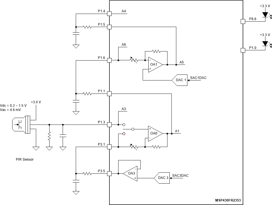
To limit the introduction of noise (which could lead to false triggering of the sensor), a more optimized signal chain topology is used as shown in Figure 2-21. It consists of two cascaded gain stages, each of which has an offset voltage that is dynamically controlled via a DAC. The first stage uses a non-inverting topology whose offset voltage is intended to track the DC offset of the PIR sensor. This is accomplished by sampling the amplifier output, computing the input-referenced voltage magnitude, and then controlling the DAC output based on a moving average of this signal. This allows for a large gain to be applied across the full DC bias range of the sensor without resulting in saturation of the amplifier output. Similarly, the second stage uses an inverting topology whose offset is varied to keep the output within the full-scale range of the sampling ADC. This extends the dynamic range of the sampling, allowing for higher gain to be applied and therefore more distant or minor motion events to be detected.
Although this signal chain uses multiple analog components and is more complex than conventional R/C-based filters, the high level of analog integration in Texas Instruments' MSP430FR235x family enables the full signal chain to be integrated into a single-chip solution. In doing so, additional flexibility is obtained in the gain-bandwidth of the signal chain (which can be controlled via firmware) as well as the processing applied to the PIR sensor output and the algorithms used to determine motion.
 Figure 2-21 PIR and MSP430™ Based Motion Detection Design Block Diagram