TIDUEZ4 May 2021
- Description
- Resources
- Features
- Applications
- 5
- 1System Description
-
2System Overview
- 2.1 Block Diagram
- 2.2 Highlighted Products
- 2.3 Design Considerations
- 3Hardware, Software, Testing Requirements, and Test Results
- 4Design and Documentation Support
- 5About the Author
2.3.1 Input Power: Battery and USB
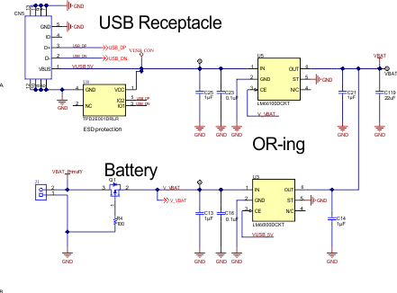
The wireless camera module is powered with batteries. The camera can be programmed and configured using an USB interface. The USB interface can also be used for powering the wireless camera. A power supply input ORing scheme is used as the USB cable can be plugged-in when the batteries are installed.
A P-FET is used for reverse polarity protection at the battery input. An electro-static discharge (ESD) protection diode TPD2E001 is used at the USB port.
Two LM66100 Ideal Diodes are used together for ORing between these power supplies: battery and USB. The circuit shown in Figure 2-18, connects the active-low chip enable (CE) of each device to the opposite power source. The highest voltage rail will be selected using a make-before-break logic in this configuration which prevents any reverse current flow between the supplies and avoids the need of a dedicated reverse current blocking comparator.
 Figure 2-18 Dual-Ideal Diode ORing Circuit in the
Design
Figure 2-18 Dual-Ideal Diode ORing Circuit in the
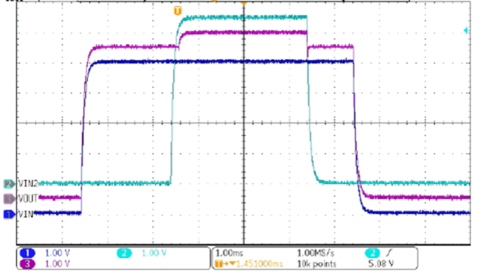
DesignIn the absence of USB power, the battery powers the system. If the battery is disconnected, USB port will power the camera module. In presence of both battery and USB, highest supply will take priority. The scope shot in Figure 2-19 shows the output voltage (VOUT) being initially powered by VIN1. When VIN2 is applied, it powers VOUT because it is a higher voltage. When VIN2 is removed, VOUT is again powered by VIN1.
 Figure 2-19 Dual Ideal Diode ORing
Behavior