TIDUEZ4 May   2021


  1.   Description
  2.   Resources
  3.   Features
  4.   Applications
  5.   5
  6. 1System Description
  7. 2System Overview
    1. 2.1 Block Diagram
    2. 2.2 Highlighted Products
      1. 2.2.1 SimpleLink MCU
        1. 2.2.1.1 CC3235MODS
        2. 2.2.1.2 CC1352R LaunchPad
          1. 2.2.1.2.1 CC1352R
      2. 2.2.2 Power
        1. 2.2.2.1 TPS63802
        2. 2.2.2.2 TPS63900
        3. 2.2.2.3 TPS62825
        4. 2.2.2.4 TPS7A03
        5. 2.2.2.5 TPS7A20
        6. 2.2.2.6 TPS62840
        7. 2.2.2.7 TPS22919
        8. 2.2.2.8 LM66100
      3. 2.2.3 Peripherals
        1. 2.2.3.1 OPT3004
        2. 2.2.3.2 DRV8837C
        3. 2.2.3.3 TPA2011
        4. 2.2.3.4 TLV61048
      4. 2.2.4 OmniVision Video Encoder OA7000
      5. 2.2.5 OmniVision Image Sensor SP2329
      6. 2.2.6 YTOT Lens Module
    3. 2.3 Design Considerations
      1. 2.3.1  Input Power: Battery and USB
      2. 2.3.2  Power Requirements
      3. 2.3.3  Camera Wake-up and Day or Night Sensing
        1. 2.3.3.1 PIR and MSP430 Based Motion Detection Design for Low Cost and High Performance
      4. 2.3.4  Battery Gauging
      5. 2.3.5  IR LED Illumination
      6. 2.3.6  IR Cut Filter
      7. 2.3.7  Audio
      8. 2.3.8  System Operation
      9. 2.3.9  Wi-Fi and Host Subsystem
      10. 2.3.10 Firmware Control
        1. 2.3.10.1 Application Flow
  8. 3Hardware, Software, Testing Requirements, and Test Results
    1. 3.1 Hardware
    2. 3.2 Software
    3. 3.3 Setup
      1. 3.3.1 Configuration Steps for Video over Wi-Fi
      2. 3.3.2 (Optional) Flash OA7000 With Latest Firmware or Stream Video Over USB
      3. 3.3.3 Audio Streaming
      4. 3.3.4 LPSTK-CC1352R Configuration Steps for Camera Module
    4. 3.4 Test Results
      1. 3.4.1 Power Supply Rails and Current Consumption
      2. 3.4.2 Battery Life Calculations
      3. 3.4.3 Video Streaming
      4. 3.4.4 IR LED Drive
  9. 4Design and Documentation Support
    1. 4.1 Design Files
      1. 4.1.1 Schematics
      2. 4.1.2 Bill of Materials
    2. 4.2 Software
    3. 4.3 Support Resources
    4. 4.4 References
    5. 4.5 Trademarks
  10. 5About the Author

TPS62825

The TPS62825 and TPS62821 are synchronous step-down converters based on the DCS-Controlâ„¢ (Direct Control with Seamless Transition into Power-Save Mode) topology with an adaptive constant on-time control and a stabilized switching frequency. It operates in PWM (pulse width modulation) mode for medium to heavy loads and in PSM (power save mode) at light load conditions, keeping the output voltage ripple small. The nominal switching frequency is about 2.2 MHz with a small and controlled variation over the input voltage range. As the load current decreases, the converter enters PSM, reducing the switching frequency to keep efficiency high over the entire load current range. Since combining both PWM and PSM within a single building block, the transition between modes is seamless and without effect on the output voltage.

The TPS62825 offers excellent DC voltage and fast load transient regulation with low output voltage ripple that is ideal for powering the video processor.
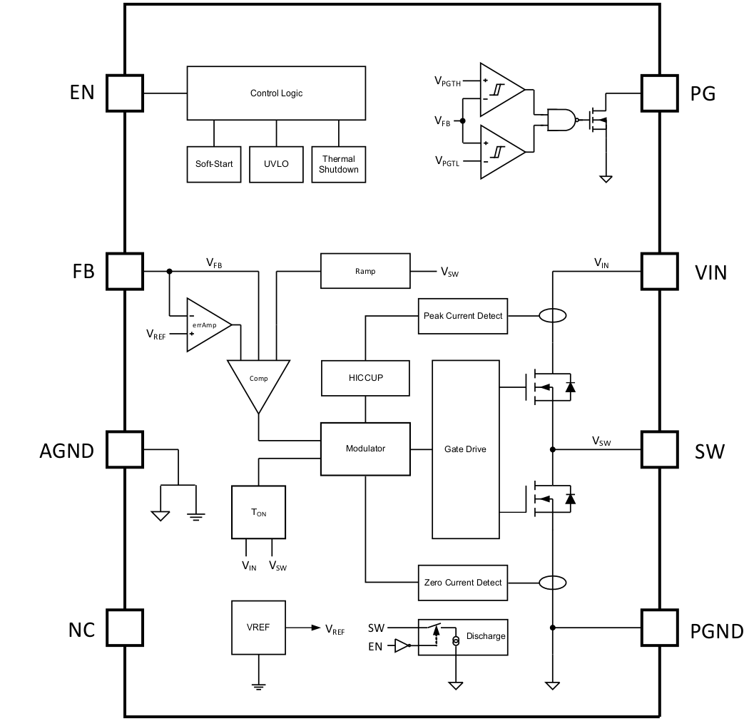
GUID-1B67E8C0-414E-445A-B044-99B20AEA96DC-low.gif Figure 2-8 TPS62825 Functional Block Diagram