TIDUEZ4 May 2021
- Description
- Resources
- Features
- Applications
- 5
- 1System Description
-
2System Overview
- 2.1 Block Diagram
- 2.2 Highlighted Products
- 2.3 Design Considerations
- 3Hardware, Software, Testing Requirements, and Test Results
- 4Design and Documentation Support
- 5About the Author
2.3.10.1 Application Flow
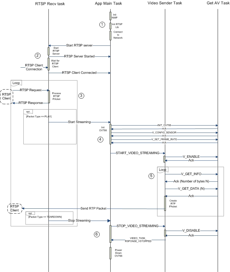
Figure 2-29 shows the application flow.
 Figure 2-29 Application Flow Diagram
- The App Main Task initializes the network processor, initializes the RTSP library, and connects the device to a network.
- When the device is connected to the network, the RTSP Recv Task starts a TCP server and waits for an RTSP client to connect.
- When the client is connected and an RTSP packet is received, RTSP Recv Task processes the packet. If a PLAY packet is received, a message is sent to App Main Task to start the streaming. If a TEARDOWN packet is received, a message is sent to App Main Task to stop the streaming.
- When a start streaming message is received, the App Main Task powers on the OA7000 subsystem, downloads the OA7000 firmware, and configures the sensor. Afterward, an initialization message is sent to the Video Sender Task to start the video streaming.
- When the message to start video streaming is received, the Video Sender Task sends the V_ENABLE message to enable the video on the OA7000. After enabling, the Video Sender Task requests the available data info and, upon receiving valid data information, gets the video data in a loop until a stop streaming message is received.
- If the stop streamlining message is received by the App Main Task, a message is sent to the Video Sender Task to stop streaming and wait for an acknowledgment message. Once the acknowledgment is received, the OA7000 subsystem is powered down.
For lower current consumption, while the system is not streaming, the CC3235MODS MCU can be configured in hibernate mode to wake-up off a trigger from the CC1352R LaunchPad. An example software for the CC1352R LaunchPad is found in the design folder at TIDA-010224. This power management scheme is selected to allow for wake-up using either PIR based trigger or video-doorbell, or network trigger.
For static CC3235MODS current measurements across power modes, see the CC3235MODx and CC3235MODAx SimpleLink™ Wi-Fi CERTIFIED™ Dual-Band Wireless MCU Modules Data Sheet.