TIDUF44 January   2024


  1.   1
  2.   Description
  3.   Resources
  4.   Features
  5.   Applications
  6.   6
  7. 1System Description
    1. 1.1 Key System Specifications
  8. 2System Overview
    1. 2.1 Block Diagram
    2. 2.2 Highlighted Products
      1. 2.2.1 BQ76907
      2. 2.2.2 BQ76905
      3. 2.2.3 BQ77207
      4. 2.2.4 MSPM0L1106
      5. 2.2.5 TCAN1042
      6. 2.2.6 TPSM365R6V5
      7. 2.2.7 TLV704
      8. 2.2.8 TMP61
  9. 3System Design Theory
    1. 3.1 Primary Protection Design
    2. 3.2 Secondary Protection
    3. 3.3 Other Circuit Design
  10. 4Hardware, Software, Testing Requirements, and Test Results
    1. 4.1 Hardware Requirements
    2. 4.2 Software Requirements
    3. 4.3 Test Setup
    4. 4.4 Test Results
      1. 4.4.1 Cell Voltage Accuracy
      2. 4.4.2 Pack Current Accuracy
      3. 4.4.3 Protection
      4. 4.4.4 Cell Balancing
      5. 4.4.5 Working Modes Transition
      6. 4.4.6 Thermal Performance
  11. 5Design and Documentation Support
    1. 5.1 Design Files
      1. 5.1.1 Schematics
      2. 5.1.2 BOM
    2. 5.2 Tools and Software
    3. 5.3 Documentation Support
    4. 5.4 Support Resources
    5. 5.5 Trademarks
  12. 6About the Author

Working Modes Transition

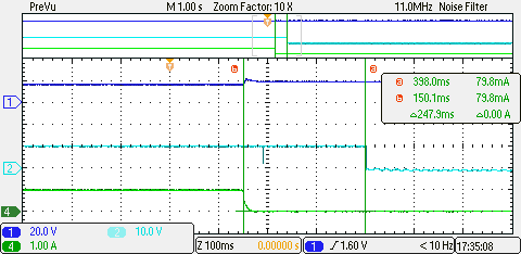
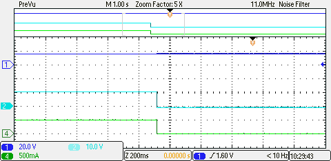
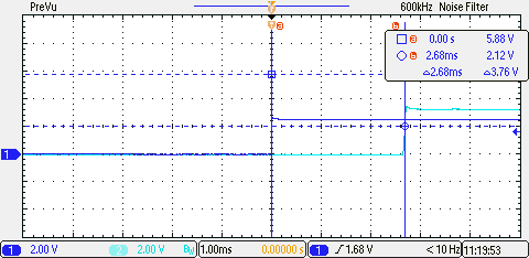
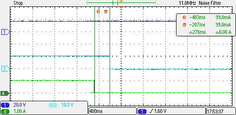
The BQ76905 has 4 working modes: normal mode, sleep mode, deep sleep mode, and shutdown mode. When the pack is charging or discharging, the pack is in normal mode. Sleep mode is when no charging nor discharging, the pack is waiting for charger or load attachment. Deep sleep mode is a low current consumption modem, internal LDO is active can keep MCU powered. Shutdown mode is a very low current consumption mode which saves energy and helps to avoid battery over discharge when the pack or cell voltage is low, only wake by external trigger. Different working mode transition are shown in Figure 4-11 to Figure 4-14.
GUID-20231006-SS0I-SDH2-BRD3-MC1JGHBT0SLB-low.png
CH1 (Blue): Trigger signal, CH2 (Cyan): 3.3-V output
Figure 4-11 Deep Sleep Mode to Normal Mode
GUID-20230906-SS0I-ZVP4-2QCJ-R8K9SVL3KTRB-low.png
CH1 (Blue): Battery voltage, CH2 (Cyan): DSG V_gs, CH4 (Green): Discharge Current
Figure 4-12 Discharge Mode to Sleep Mode
GUID-20230906-SS0I-V2GH-RP2V-5HRBS3954MCT-low.png
CH1 (Blue): Battery voltage, CH2 (Cyan): CHG V_gs, CH4 (Green): Charge Current
Figure 4-13 Charge Mode to Sleep Mode
GUID-20230906-SS0I-HKDQ-84FS-HZ7Z1VWDM4JK-low.png
CH1 (Blue): Battery voltage, CH2 (Cyan):CHG V_gs, CH4 (Green): Charge Current
Figure 4-14 Charge to Deep Sleep Mode (Enter Deep Sleep Mode Through I2C Command)