SNLS316G September 2009 – December 2015 DS90UR907Q-Q1
PRODUCTION DATA.
- 1 Features
- 2 Applications
- 3 Description
- 4 Revision History
- 5 Pin Configuration and Functions
-
6 Specifications
- 6.1 Absolute Maximum Ratings
- 6.2 ESD Ratings—JEDEC
- 6.3 ESD Ratings—IEC and ISO
- 6.4 Recommended Operating Conditions
- 6.5 Thermal Information
- 6.6 DC Electrical Characteristics
- 6.7 Recommended Timing for the Serial Control Bus
- 6.8 Switching Characteristics
- 6.9 DC and AC Serial Control Bus Characteristics
- 6.10 Typical Characteristics
-
7 Detailed Description
- 7.1 Overview
- 7.2 Functional Block Diagram
- 7.3 Feature Description
- 7.4 Device Functional Modes
- 7.5 Programming
- 8 Application and Implementation
- 9 Power Supply Recommendations
- 10Layout
- 11Device and Documentation Support
- 12Mechanical, Packaging, and Orderable Information
Package Options
Mechanical Data (Package|Pins)
- NJK|36
Thermal pad, mechanical data (Package|Pins)
Orderable Information
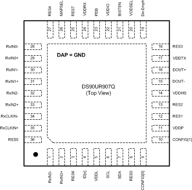
5 Pin Configuration and Functions
NJK Package
36-Pin WQFN
Top View

Pin Functions
| PIN | I/O, TYPE | DESCRIPTION | |
|---|---|---|---|
| NAME | NO. | ||
| FPD-LINK INPUT INTERFACE | |||
| RxIN[3:0]+ | 2, 33, 31, 29 | I, LVDS | True LVDS Data Input This pair requires an external 100 Ω termination for standard LVDS levels. |
| RxIN[3:0]- | 1, 34, 32, 30, 28 | I, LVDS | Inverting LVDS Data Input This pair requires an external 100 Ω termination for standard LVDS levels. |
| RxCLKIN+ | 35 | I, LVDS | True LVDS Clock Input This pair requires an external 100 Ω termination for standard LVDS levels. |
| RxCLKIN- | 34 | I, LVDS | Inverting LVDS Clock Input This pair requires an external 100 Ω termination for standard LVDS levels. |
| CONTROL AND CONFIGURATION | |||
| PDB | 23 | I, LVCMOS w/ pulldown |
Power-down Mode Input PDB = 1, Device is enabled (normal operation). Refer to Power-Up Requirements and PDB Pin in the Applications Information Section. PDB = 0, Device is powered down When the Device is in the power-down state, the driver outputs (DOUT+/-) are both logic high, the PLL is shutdown, IDD is minimized. Control Registers are RESET. |
| VODSEL | 20 | I, LVCMOS w/ pulldown |
Differential Driver Output Voltage Select — Pin or Register Control VODSEL = 1, LVDS VOD is ±450 mV, 900 mVp-p (typical) — Long Cable / De-E Applications VODSEL = 0, LVDS VOD is ±300 mV, 600 mVp-p (typical) |
| De-Emph | 19 | I, Analog w/ pullup |
De-Emphasis Control — Pin or Register Control De-Emph = open (float) - disabled To enable De-emphasis, tie a resistor from this pin to GND or control through register. See Table 3 |
| MAPSEL | 26 | I, LVCMOS w/ pulldown |
FPD-Link Map Select — Pin or Register Control MAPSEL = 1, MSB on RxIN3+/-. Figure 17 MAPSEL = 0, LSB on RxIN3+/-. Figure 16 |
| CONFIG[1:0] | 10, 9 | I, LVCMOS w/ pulldown |
Operating Modes Determine the device operating mode and interfacing device. Table 1 CONFIG[1:0] = 00: Interfacing to DS90UR906 or DS90UR908, Control Signal Filter DISABLED CONFIG[1:0] = 01: Interfacing to DS90UR906 or DS90UR908, Control Signal Filter ENABLED CONFIG [1:0] = 10: Interfacing to DS90UR124, DS99R124 CONFIG [1:0] = 11: Interfacing to DS90C124 |
| ID[x] | 4 | I, Analog | Serial Control Bus Device ID Address Select — Optional Resistor to Ground and 10-kΩ pullup to 1.8-V rail. See Table 5. |
| SCL | 6 | I, LVCMOS | Serial Control Bus Clock Input - Optional SCL requires an external pullup resistor to VDDIO. |
| SDA | 7 | I/O, LVCMOS Open Drain |
Serial Control Bus Data Input / Output - Optional SDA requires an external pullup resistor VDDIO. |
| BISTEN | 21 | I, LVCMOS w/ pulldown |
BIST Mode — Optional BISTEN = 1, BIST is enabled BISTEN = 0, BIST is disabled |
| RES[7:0] | 25, 3, 36, 27, 18, 13, 12, 8 | I, LVCMOS w/ pulldown |
Reserved - tie LOW |
| FPD-LINK II SERIAL INTERFACE | |||
| DOUT+ | 16 | O, LVDS | True Output. The output must be AC Coupled with a 100 nF capacitor. |
| DOUT- | 15 | O, LVDS | Inverting Output. The output must be AC Coupled with a 100 nF capacitor. |
| POWER AND GROUND | |||
| VDDL | 5 | Power | Logic Power, 1.8 V ±5% |
| VDDP | 11 | Power | PLL Power, 1.8 V ±5% |
| VDDHS | 14 | Power | TX High Speed Logic Power, 1.8 V ±5% |
| VDDTX | 17 | Power | Output Driver Power, 1.8 V ±5% |
| VDDRX | 24 | Power | RX Power, 1.8 V ±5% |
| VDDIO | 22 | Power | LVCMOS I/O Power and FPD-Link I/O Power 1.8 V ±5% OR 3.3 V ±10% |
| GND | DAP | Ground | DAP is the large metal contact at the bottom side, located at the center of the WQFN package. Connect to the ground plane (GND) with at least 9 vias. |