SBAU378A September 2021 – January 2022 ADS1148 , ADS1248
- Trademarks
- 1Introduction
- 2Getting Started With the ADS1x48EVM
-
3ADS1x48EVM Overview
- 3.1 Analog and Digital Power Supplies
- 3.2 Voltage Reference Options
- 3.3 Clock Options
- 3.4 Digital Interface
- 3.5
Analog Input Connections
- 3.5.1 Connecting a Thermocouple to J5 on the ADS1x48EVM
- 3.5.2 Connecting a Thermistor to J5 on the ADS1x48EVM
- 3.5.3
Connecting an RTD to J6 on the ADS1x48EVM
- 3.5.3.1 Connecting a 2-Wire RTD Using a Low-Side RREF to J6 on the ADS1x48EVM
- 3.5.3.2 Connecting a 2-Wire RTD Using a High-Side RREF to J6 on the ADS1x48EVM
- 3.5.3.3 Connecting a 3-Wire RTD Using One IDAC and a Low-Side RREF to J6 on the ADS1x48EVM
- 3.5.3.4 Connecting a 3-Wire RTD Using One IDAC and a High-Side RREF to J6 on the ADS1x48EVM
- 3.5.3.5 Connecting a 3-Wire RTD Using Two IDACs and a Low-Side RREF to J6 on the ADS1x48EVM
- 3.5.3.6 Connecting a 3-Wire RTD Using Two IDACs and a High-Side RREF to J6 on the ADS1x48EVM
- 3.5.3.7 Connecting a 4-Wire RTD Using a Low-Side RREF to J6 on the ADS1x48EVM
- 3.5.3.8 Connecting a 4-Wire RTD Using a High-Side RREF to J6 on the ADS1x48EVM
- 3.5.3.9 Summary of ADS1x48EVM RTD Configuration Settings
- 3.5.4 Connecting a General-Purpose Input to J5 on the ADS1x48EVM
- 4ADS1x48EVM GUI
- 5Bill of Materials, Printed Circuit Board Layout, and Schematic
- 6Revision History
4.1 Home
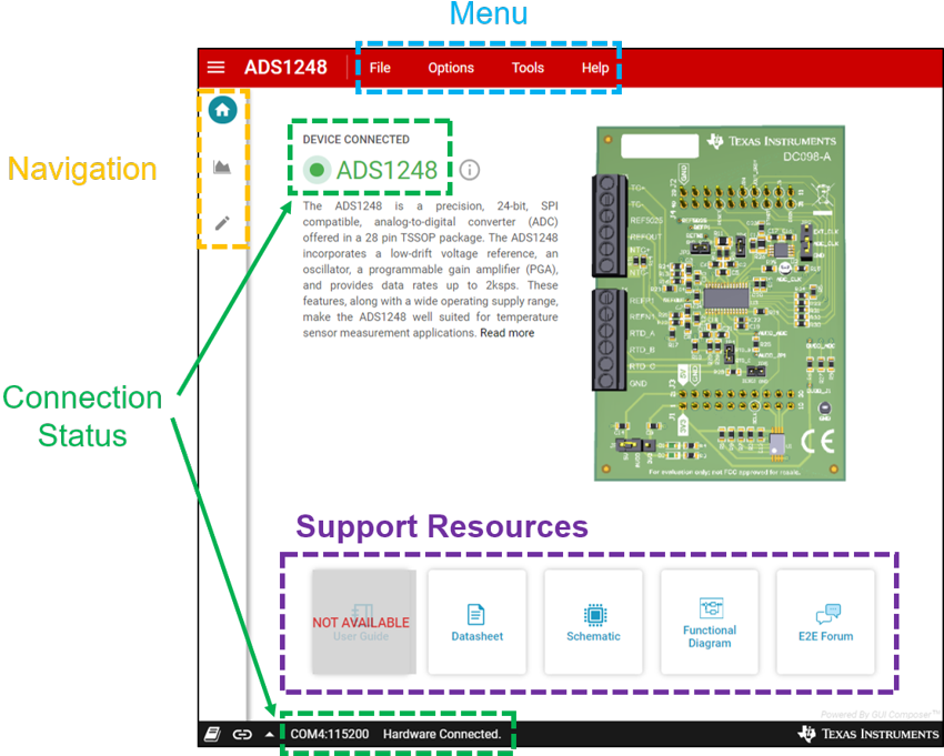
The Home page is the GUI start-up landing page. The Home page provides a high-level overview of the ADS1x48 including a device description and a 3D view of the EVM PCB. Highlighted in orange in the upper-left corner of Figure 4-2 is a vertical Navigation bar for the various GUI pages, including:
- Home
- Data Capture
- Register Map
The horizontal Menu bar at the top of the GUI shows the following menu options, which are highlighted in blue in Figure 4-2 and are discussed in more detail in Section 4.1.1:
- File
- Options
- Tools
- Help
Quick links to Support Resources are shown at the bottom of the Home page. These links are highlighted in purple in Figure 4-2 and include the EVM user's guide, schematic, and ADC data sheet. Finally, a successfully connected EVM displays as Device Connected in the top left and as Hardware Connected in the status ribbon. Both of these indicators are highlighted in green in Figure 4-2.
 Figure 4-2 ADS1x48EVM GUI Home
Page
Figure 4-2 ADS1x48EVM GUI Home
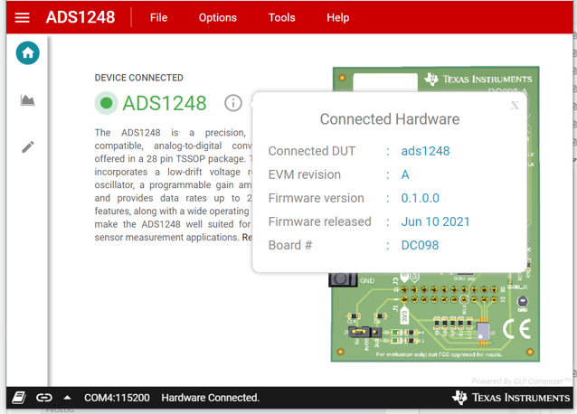
PageOne other important feature of the Home page is an information icon next to the device name. Clicking the icon, as shown in Figure 4-3, displays specific information regarding the ADS1x48EVM.
 Figure 4-3 Connected Hardware
Information