SBOA418 july 2023 OPA2197-Q1 , OPA392
- 1
- Abstract
- Trademarks
- 1Introduction: Open-Loop Output Impedance (RO)
- 2Overview: Closed-Loop Amplifier Stability
- 3Example, Calculate Optimal Isolation Resistance to Drive Large Load Capacitance
- 4RO, RISO, and Capacitive Load Drive
- 5Derive Equation for Optimal Isolation Resistance
- 6Summary
- 7References
1 Introduction: Open-Loop Output Impedance (RO)
The ideal op amp has infinite input impedance and zero output impedance. In practice, every real amplifier has a non-zero output impedance typically in the range of Ω to kΩ. Texas Instruments op amp data sheets include a plot of the open-loop output impedance (RO) over frequency. RO is not to be confused with the closed-loop output impedance (ROUT), although the two are closely related by the loop gain.
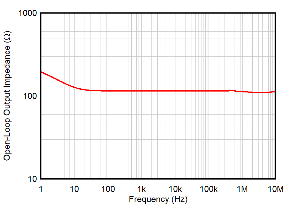
Figure 1-1 shows the open-loop output impedance over frequency for the OPA392, which is flat at approximately 120 Ω across frequency. This flat portion of the curve implies that the open-loop output impedance acts as a resistor (RO) across the effective bandwidth of the amplifier. Some amplifiers have an output impedance that changes over frequency, implying a complex impedance (ZO). The analysis in this document applies to amplifiers that have a flat, resistive output impedance across the effective bandwidth of the amplifier.
 Figure 1-1 Open-Loop Output Impedance vs Frequency, OPA392
RO is also specified in the electrical characteristics section of the data sheet, which confirms the resistance is 120 Ω. This data sheet specification for RO is used to determine an optimal value for RISO when driving a large capacitive load, as described in Section 3.
| RO | Open-loop output impedance | f = 1 MHz | 120 | Ω |