SLAU919 November   2023


  1.   1
  2.   Description
  3.   Get Started
  4.   Features
  5.   Applications
  6.   6
  7. 1Evaluation Module Overview
    1. 1.1 Introduction
    2. 1.2 Kit Contents
    3. 1.3 Specification
    4. 1.4 Device Information
  8. 2Hardware
    1. 2.1 Hardware Setup
      1. 2.1.1 Hardware Theory of Operation
      2. 2.1.2 Jumper Definitions
      3. 2.1.3 Connector Definitions
      4. 2.1.4 Test Points
    2. 2.2 Hardware Overview
      1. 2.2.1 Electrostatic Discharge Caution
      2. 2.2.2 Connecting the FTDI Digital Controller
      3. 2.2.3 SPI Configuration
      4. 2.2.4 I2C Configuration
  9. 3Software
    1. 3.1 Software Setup
      1. 3.1.1 Software Installation
    2. 3.2 Software Overview
      1. 3.2.1 Launching the Software
      2. 3.2.2 Software Features
        1. 3.2.2.1 Low Level Configuration Page
        2. 3.2.2.2 High Level Configuration Page
  10. 4Hardware Design Files
    1. 4.1 Schematics
    2. 4.2 PCB Layout
    3. 4.3 Bill of Materials
  11. 5Additional Information
    1.     Trademarks
  12. 6Related Documentation

Low Level Configuration Page

Figure 4-8 shows the Low Level Configuration page of the DAC805xxEVM GUI. This page allows direct access to all registers on the DAC80501. Figure 4-9 shows the Low Level Configuration page for the DAC80502.

The Register Map section in the center of the page lists all the registers. Directly above the Register Map section are four buttons that allow for read and write access to all registers.

Select a register on the Register Map list to show a description of the values in that register, as well as information on the register address, default value, size, and current value. Data are written to the registers by entering a value in the value column of the GUI.
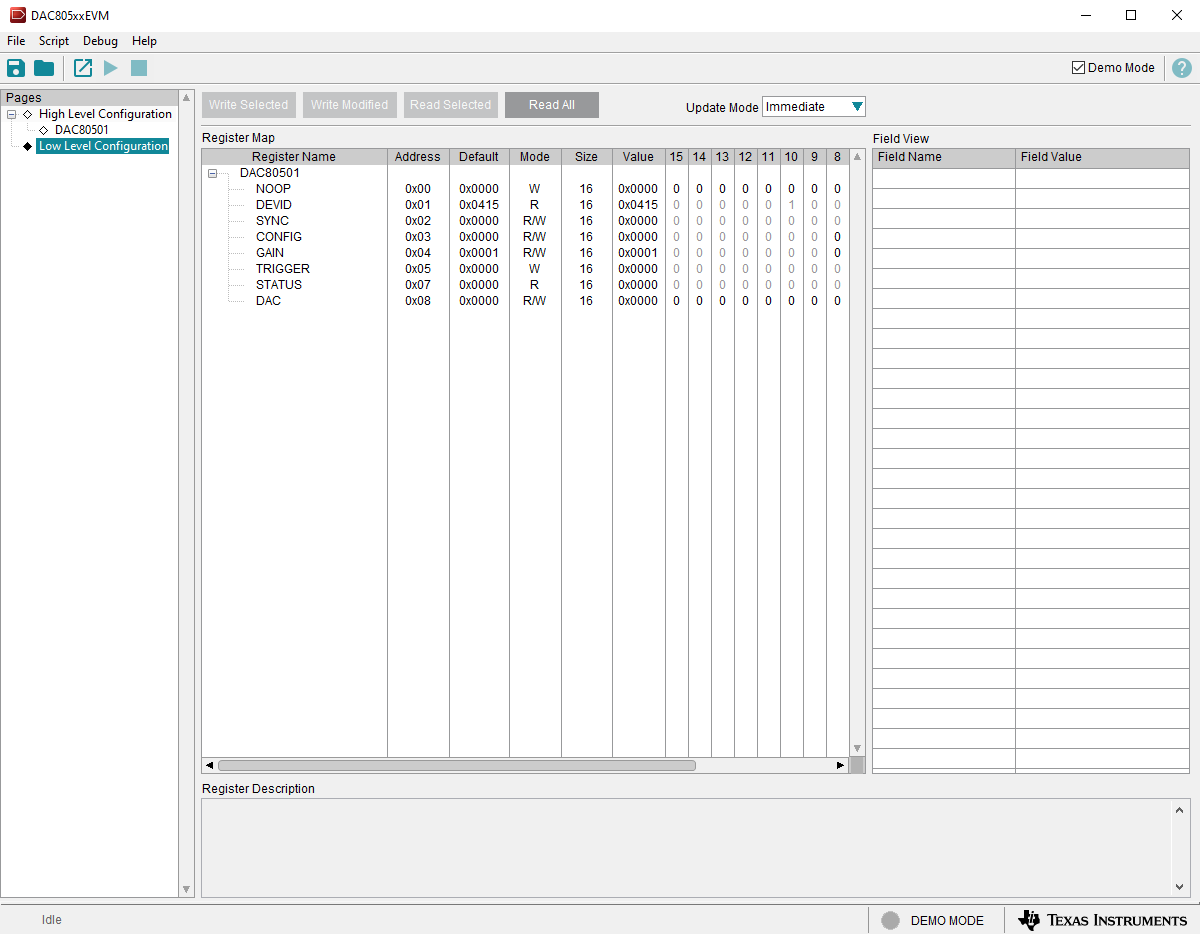
GUID-20231023-SS0I-TWDB-RZF2-BCGRVPTZGXQ9-low.pngFigure 3-8 DAC80501 Low Level Configuration Page
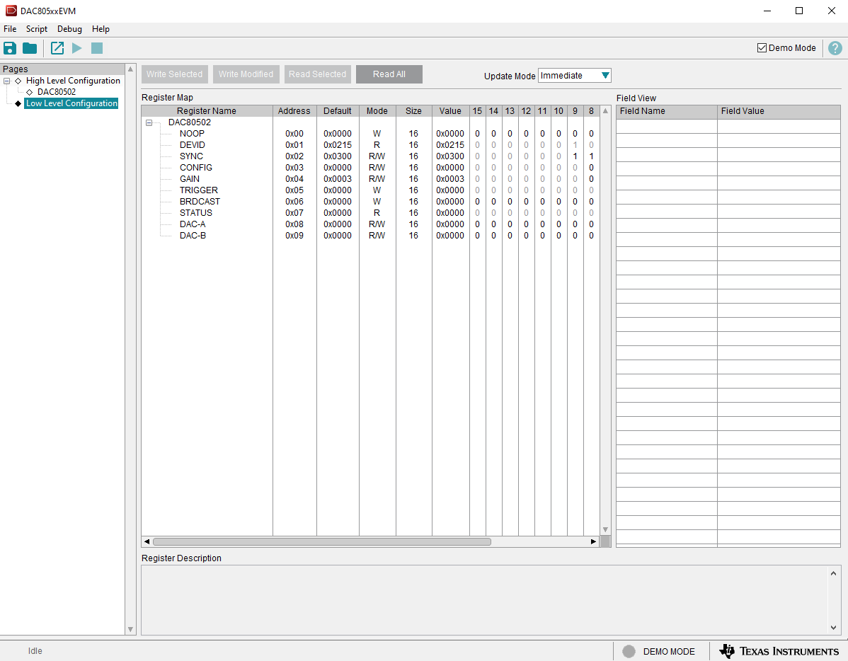
GUID-20231023-SS0I-GMKJ-RFVN-J1HNZ08WSDFT-low.pngFigure 3-9 DAC80502 Low Level Configuration Page