SNOA961A February 2017 – February 2023 LDC2112 , LDC2114 , LDC3114 , LDC3114-Q1
- Inductive Touch System Design Guide for HMI Button Applications
- 1Mechanical Design
- 2Sensor Design
- 3Summary
- 4Revision History
1.4.3 Spacing Between Target and Sensor
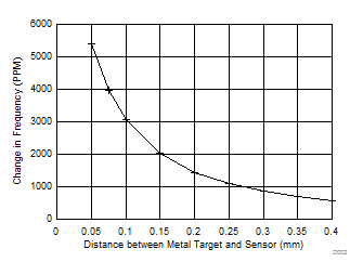
The spacing between the metal target and PCB sensor is important for both electrical and mechanical considerations. As the metal target approaches the coil sensor, it can interact with more of the electromagnetic field. Therefore for the same deflection (for example, 1 µm) at a closer nominal distance, the amount of inductance shift increases, which leads to a larger change in frequency (see #T4726003-15). In other words, if the target is closer to the sensor, the system sensitivity is higher.
 Figure 1-5 Simulated Change in Frequency (PPM) for 1-µm
Deflection vs Target Distance (mm)
Figure 1-5 Simulated Change in Frequency (PPM) for 1-µm
Deflection vs Target Distance (mm)However, to ensure that there is enough room for deflection and meanwhile accounting for manufacturing tolerances, TI recommends to have a nominal target-to-sensor distance of 0.1 to 0.2 mm. This spacing can be achieved by creating recessed area in the metal facing the sensor for systems where the PCB is placed flush to the metal, or by using a small spacer between the metal and the PCB sensor with a cutout to allow the metal to deflect, as shown in #T4726003-16.
 Figure 1-6 Spacer Options
Maintaining a consistent separation between the sensor and the target is critical to ensure effective sensing. If spacers are used, the material should be non-compressible and have a low temperature coefficient, so that the thickness does not vary over time or environmental conditions.