SNOA961A February 2017 – February 2023 LDC2112 , LDC2114 , LDC3114 , LDC3114-Q1
- Inductive Touch System Design Guide for HMI Button Applications
- 1Mechanical Design
- 2Sensor Design
- 3Summary
- 4Revision History
1.1 Theory of Operation
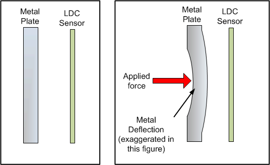
Consider a flat metal plate held at a fixed distance from an inductive coil sensor, as shown in #T4726003-1. If a force is applied onto the metal plate, the metal will deform slightly. For example, with a 1 N force, which is approximately the weight of a computer mouse, a 1-mm thick aluminum plate that is 15 mm × 15 mm will deform by about 0.2 µm. This deformation moves the opposite side of the plate closer to the LDC sensor. When the force is removed, the plate will return to its original unstressed shape.
When the conductive material is in close proximity to the inductor, the magnetic field will induce circulating eddy currents on the surface of the conductor. The eddy currents are a function of the distance, size, and composition of the conductor. If the conductor is deflected toward the inductor as shown in #T4726003-1, more eddy currents will be generated.
 Figure 1-1 Metal Deflection
The eddy currents generate their own magnetic field, which opposes the original field generated by the inductor. This effect reduces the inductance of the system, resulting in an increase in sensor frequency. As the conductive target moves closer to the sensor, the electromagnetic coupling between them becomes stronger. As a result, the change in sensor frequency is also more significant.