SPRUJ51 june 2023
- 1
- 1Abstract
- 2EVM Revisions and Assembly Variants
- Trademarks
-
3System Description
- 3.1 Key Features
- 3.2 Functional Block Diagram
- 3.3 AM62x-Low Power SK EVM Interface Mapping
- 3.4 Power ON OFF Procedures
- 3.5
Peripheral and Major Component Description
- 3.5.1 Clocking
- 3.5.2 Reset
- 3.5.3 OLDI Display Interface
- 3.5.4 CSI Interface
- 3.5.5 Audio Codec Interface
- 3.5.6 HDMI Display Interface
- 3.5.7 JTAG Interface
- 3.5.8 Test Automation Header
- 3.5.9 UART Interface
- 3.5.10 USB Interface
- 3.5.11 Memory Interfaces
- 3.5.12 Ethernet Interface
- 3.5.13 GPIO Port Expander
- 3.5.14 GPIO Mapping
- 3.5.15 Power
- 3.5.16 AM62x-Low Power SK EVM User Setup and Configuration
- 3.5.17 Expansion Headers
- 3.5.18 Push Buttons
- 3.5.19 I2C Address Mapping
- 4Known Issues and Modifications
- 5Revision History
- 6IMPORTANT NOTICE AND DISCLAIMER
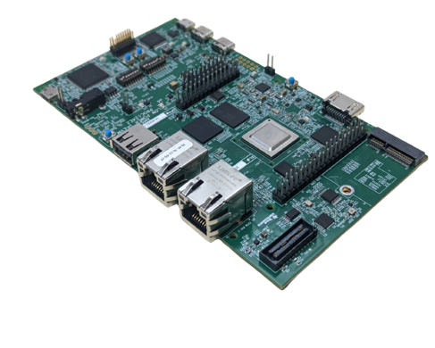
1 Abstract
This technical user’s guide describes the hardware architecture of the AM62x-Low Power SK EVM, a low cost starter kit built around the AM62x System-on-Chip (SoC). The AM62x processor comprises of a quad-core 64-bit Arm®-Cortex® A53 microprocessor, single-core Arm Cortex-R5F MCU and an Arm Cortex-M4F MCU.
The SK EVM allows the user to experience a great dual display feature through HDMI (over DPI) and LVDS, up to 2K resolution, as well as industrial communication solutions using serial, Ethernet, USB and other interfaces. Its powerful Arm performance, up to quad-core Cortex-A53 at 1.4GHz, with rich interfaces, offers good control and communication capabilities for a wide ranges of automotive applications such as automotive HMI and driver monitoring system, as well as industrial applications such as PLC, automation control, monitor/supervisor system. In addition, the SK EVM can communicate with other processors or systems, and act as a communication gateway. In addition, the SK EVM can directly operate as a standard remote I/O system or simple sensor connected to an industrial communication network. The embedded emulation logic allows for emulation and debugging using standard development tools such as Code Composer Studio™ from TI.