TIDUF33 june   2023


  1.   1
  2.   Description
  3.   Resources
  4.   Features
  5.   Applications
  6.   6
  7. 1System Description
    1. 1.1 Key System Specifications
  8. 2System Overview
    1. 2.1 Block Diagram
    2. 2.2 Design Considerations
      1. 2.2.1 Current and Voltage Controller
      2. 2.2.2 High-Resolution PWM Generation
    3. 2.3 Highlighted Products
      1. 2.3.1 TMS320F280039
      2. 2.3.2 ADS131M08
  9. 3Hardware, Software, Testing Requirements, and Test Results
    1. 3.1 Hardware Requirements
    2. 3.2 Software Requirements
      1. 3.2.1 Opening the Project Inside Code Composer Studio
      2. 3.2.2 Project Structure
      3. 3.2.3 Software Flow Diagram
    3. 3.3 Test Setup
      1. 3.3.1 Hardware Setup to Tune the Current and Voltage Loops
      2. 3.3.2 Hardware Setup to Test Bidirectional Power Flow
      3. 3.3.3 Hardware Setup for Current and Voltage Calibration
    4. 3.4 Test Procedure
      1. 3.4.1 Lab Variables Definitions
      2. 3.4.2 Lab 1. Open-Loop Current Control Single Phase
        1. 3.4.2.1 Setting Software Options for Lab 1
        2. 3.4.2.2 Building and Loading the Project and Setting up Debug Environment
        3. 3.4.2.3 Running the Code
      3. 3.4.3 Lab 2. Closed Loop Current Control Single Phase
        1. 3.4.3.1 Setting Software Options for Lab 2
        2. 3.4.3.2 Building and Loading the Project and Setting up Debug Environment
        3. 3.4.3.3 Running the Code
        4. 3.4.3.4 Current Calibration
      4. 3.4.4 Lab 3. Closed Loop Current Control Dual Phase
        1. 3.4.4.1 Setting Software Options for Lab 3
        2. 3.4.4.2 Building and Loading the Project and Setting up Debug Environment
        3. 3.4.4.3 Running the Code
      5. 3.4.5 Lab 4. Closed Loop Current and Voltage Control
        1. 3.4.5.1 Setting Software Options for Lab 4
        2. 3.4.5.2 Building and Loading the Project and Setting up Debug Environment
        3. 3.4.5.3 Running the Code
        4. 3.4.5.4 Voltage Calibration
    5. 3.5 Test Results
      1. 3.5.1 Current Loop Load Regulation Error
      2. 3.5.2 Voltage Loop Load Regulation Error
      3. 3.5.3 Voltage Transition at No Load
      4. 3.5.4 Transient Response at Start-Up
      5. 3.5.5 Bidirectional Current Switching Time
  10. 4Design and Documentation Support
    1. 4.1 Design Files
      1. 4.1.1 Schematics
      2. 4.1.2 BOM
    2. 4.2 Tools and Software
    3. 4.3 Documentation Support
    4. 4.4 Support Resources
    5. 4.5 Trademarks
  11. 5About the Author

Voltage Calibration

  1. To run this lab, make sure the hardware is set up as shown in, Section 3.3.3. E-Load can be turned off during calibration or set the E-Load Current Settings to smaller than iref_A to make sure the circuit is in constant-voltage mode. 2-points calibration method is used to calibrate gain and offset errors.
  2. To measure voltage, use a DMM.
  3. Open the SYSCONFIG page and select under the Build Options section:
    • Select Lab 4: Closed-Loop CCCV Dual Phase for the Lab.
    • Change the Phase Enabled to 0 for Dual-Phase Mode.
    • Set the Calibration Mode to 2 for voltage calibration.
    • Save the SYSCONFIG page, and run the code.
    • Open the Expression Window.
    • The output current is updated using BT2PH_userParam_V_I_chm->ibatCal_pu parameter.
    • Set the BT2PH_enableRelay_bool to 1 to enable the output relay.
    • Set the BT2PH_userParam_V_I_chm->en_bool = 1.
    • Set the BT2PH_userParam_V_I_chm->vbatCal_pu to "0.2" and "0.6", and note the output voltage readings.
    • Update the actual output voltage readings in bt2ph_cal.h file.

    #define BT2PH_VBAT_ACTUAL_CH1_P1_V ((float32_t)1.1995)

    #define BT2PH_VBAT_ACTUAL_CH1_P2_V ((float32_t)3.599)

    • Set the Calibration Mode to 0 disable calibration.
  4. When using non-powerSuite version of the project, Build Settings are directly modified in the solution_settings.h file:

    #define LAB_NUMBER (4)

    #define PHASE_NUMBER (0)

    #define CALIBRATION_ENABLED (true)

    #define CALIBRATION_MODE (2)

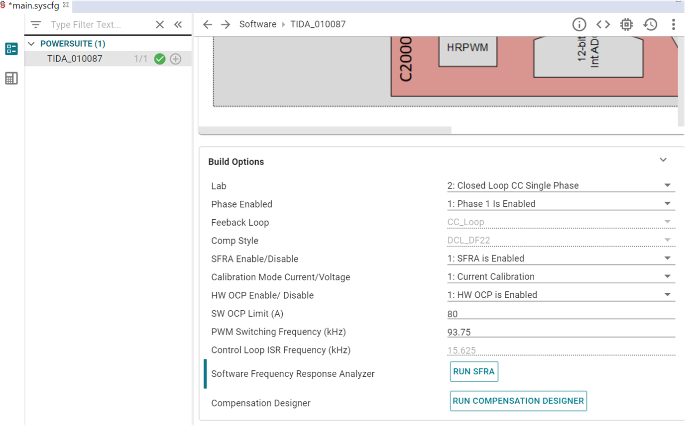
GUID-20230628-SS0I-HGX6-QSZP-8ZG3L3DSWXBX-low.png Figure 3-28 Build Options for Current Calibration