TIDUF33 june   2023


  1.   1
  2.   Description
  3.   Resources
  4.   Features
  5.   Applications
  6.   6
  7. 1System Description
    1. 1.1 Key System Specifications
  8. 2System Overview
    1. 2.1 Block Diagram
    2. 2.2 Design Considerations
      1. 2.2.1 Current and Voltage Controller
      2. 2.2.2 High-Resolution PWM Generation
    3. 2.3 Highlighted Products
      1. 2.3.1 TMS320F280039
      2. 2.3.2 ADS131M08
  9. 3Hardware, Software, Testing Requirements, and Test Results
    1. 3.1 Hardware Requirements
    2. 3.2 Software Requirements
      1. 3.2.1 Opening the Project Inside Code Composer Studio
      2. 3.2.2 Project Structure
      3. 3.2.3 Software Flow Diagram
    3. 3.3 Test Setup
      1. 3.3.1 Hardware Setup to Tune the Current and Voltage Loops
      2. 3.3.2 Hardware Setup to Test Bidirectional Power Flow
      3. 3.3.3 Hardware Setup for Current and Voltage Calibration
    4. 3.4 Test Procedure
      1. 3.4.1 Lab Variables Definitions
      2. 3.4.2 Lab 1. Open-Loop Current Control Single Phase
        1. 3.4.2.1 Setting Software Options for Lab 1
        2. 3.4.2.2 Building and Loading the Project and Setting up Debug Environment
        3. 3.4.2.3 Running the Code
      3. 3.4.3 Lab 2. Closed Loop Current Control Single Phase
        1. 3.4.3.1 Setting Software Options for Lab 2
        2. 3.4.3.2 Building and Loading the Project and Setting up Debug Environment
        3. 3.4.3.3 Running the Code
        4. 3.4.3.4 Current Calibration
      4. 3.4.4 Lab 3. Closed Loop Current Control Dual Phase
        1. 3.4.4.1 Setting Software Options for Lab 3
        2. 3.4.4.2 Building and Loading the Project and Setting up Debug Environment
        3. 3.4.4.3 Running the Code
      5. 3.4.5 Lab 4. Closed Loop Current and Voltage Control
        1. 3.4.5.1 Setting Software Options for Lab 4
        2. 3.4.5.2 Building and Loading the Project and Setting up Debug Environment
        3. 3.4.5.3 Running the Code
        4. 3.4.5.4 Voltage Calibration
    5. 3.5 Test Results
      1. 3.5.1 Current Loop Load Regulation Error
      2. 3.5.2 Voltage Loop Load Regulation Error
      3. 3.5.3 Voltage Transition at No Load
      4. 3.5.4 Transient Response at Start-Up
      5. 3.5.5 Bidirectional Current Switching Time
  10. 4Design and Documentation Support
    1. 4.1 Design Files
      1. 4.1.1 Schematics
      2. 4.1.2 BOM
    2. 4.2 Tools and Software
    3. 4.3 Documentation Support
    4. 4.4 Support Resources
    5. 4.5 Trademarks
  11. 5About the Author

System Description

The battery tester equipment includes a wide variety of equipment used to test single cells, battery modules, and high-voltage battery packs. The test equipment contains precision power supplies and data acquisition systems, and is used for charging and discharging of batteries, and measures various parameters of the cells.

Figure 1-1 shows a simplified Li-Ion battery manufacturing process. The Final stage, End-of-Line Conditioning, includes cell formation and testing. Formation is a critical step in the manufacturing of Li-ion cells. During formation, the cells go through a process of initial charge and discharge, which results in the formation of the solid electrolyte interface (SEI) layer. The quality of the SEI layer impacts capacity and reliability of the battery cell. To control the formation process, precise programmable power supplies are used for charging and discharging of cells. These power supplies are called battery formation systems or battery testers. The accuracy required in battery testers for voltage and current is typically between ±0.02% and ±0.05% of full-scale.
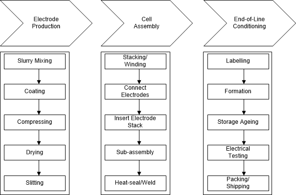
GUID-20201020-CA0I-JCC3-ZN5G-37NSBRRGFRD2-low.gif Figure 1-1 Simplified Li-Ion Battery Manufacturing Process