SLLS897F march 2008 – august 2023 ISO1176
PRODUCTION DATA
- 1
- 1 Features
- 2 Applications
- 3 Description
- 4 Revision History
- 5 Pin Configuration and Functions
-
6 Specifications
- 6.1 Absolute Maximum Ratings
- 6.2 ESD Ratings
- 6.3 Recommended Operating Conditions
- 6.4 Thermal Information
- 6.5 Power Ratings
- 6.6 Insulation Specifications
- 6.7 Safety-Related Certifications
- 6.8 Safety Limiting Values
- 6.9 Electrical Characteristics: Driver
- 6.10 Electrical Characteristics: Receiver
- 6.11 Supply Current
- 6.12 Electrical Characteristics: ISODE-Pin
- 6.13 Switching Characteristics: Driver
- 6.14 Switching Characteristics: Receiver
- 6.15 Insulation Characteristics Curves
- 6.16 Typical Characteristics
- 7 Parameter Measurement Information
- 8 Detailed Description
- 9 Application and Implementation
- 10Power Supply Recommendations
- 11Layout
- 12Device and Documentation Support
- 13Mechanical, Packaging, and Orderable Information
Package Options
Mechanical Data (Package|Pins)
- DW|16
Thermal pad, mechanical data (Package|Pins)
Orderable Information
9.2.2 Detailed Design Procedure
Isolating of a circuit insulates it from other circuits and earth, so that noise voltage develops across the insulation rather than circuit components. The most common noise threat to data-line circuits is voltage surges or electrical fast transients that occur after installation. The transient ratings of the ISO1176 standard are sufficient for all but the most severe installations. However, some equipment manufacturers use ESD generators to test equipment transient susceptibility. This practice can exceed insulation ratings. ESD generators simulate static discharges that may occur during device or equipment handling with low-energy but high-voltage transients.
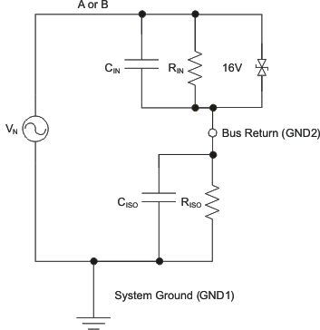
 Figure 9-2 Device
Model for Static Discharge Testing
Figure 9-2 Device
Model for Static Discharge TestingFigure 9-2 models the ISO1176 bus IO connected to a noise generator. CIN and RIN is the device, and any other stray or added capacitance or resistance across the A or B pin to GND2. CISO and RISO is the capacitance and resistance between GND1 and GND2 of the ISO1176, plus those of any other insulation (transformer, and so forth). Stray inductance is assumed to be negligible.