SNVS116E May 1998 – December 2014 LM3420
PRODUCTION DATA.
- 1 Features
- 2 Applications
- 3 Description
- 4 Revision History
- 5 Pin Configuration and Functions
- 6 Specifications
- 7 Parameter Measurement Information
- 8 Detailed Description
-
9 Application and Implementation
- 9.1 Application Information
- 9.2
Typical Application: Constant Current/Constant Voltage Li-Ion Battery Charger
- 9.2.1 Design Requirements
- 9.2.2 Detailed Design Procedure
- 9.2.3 Application Curve
- 9.2.4
Other Application Circuits
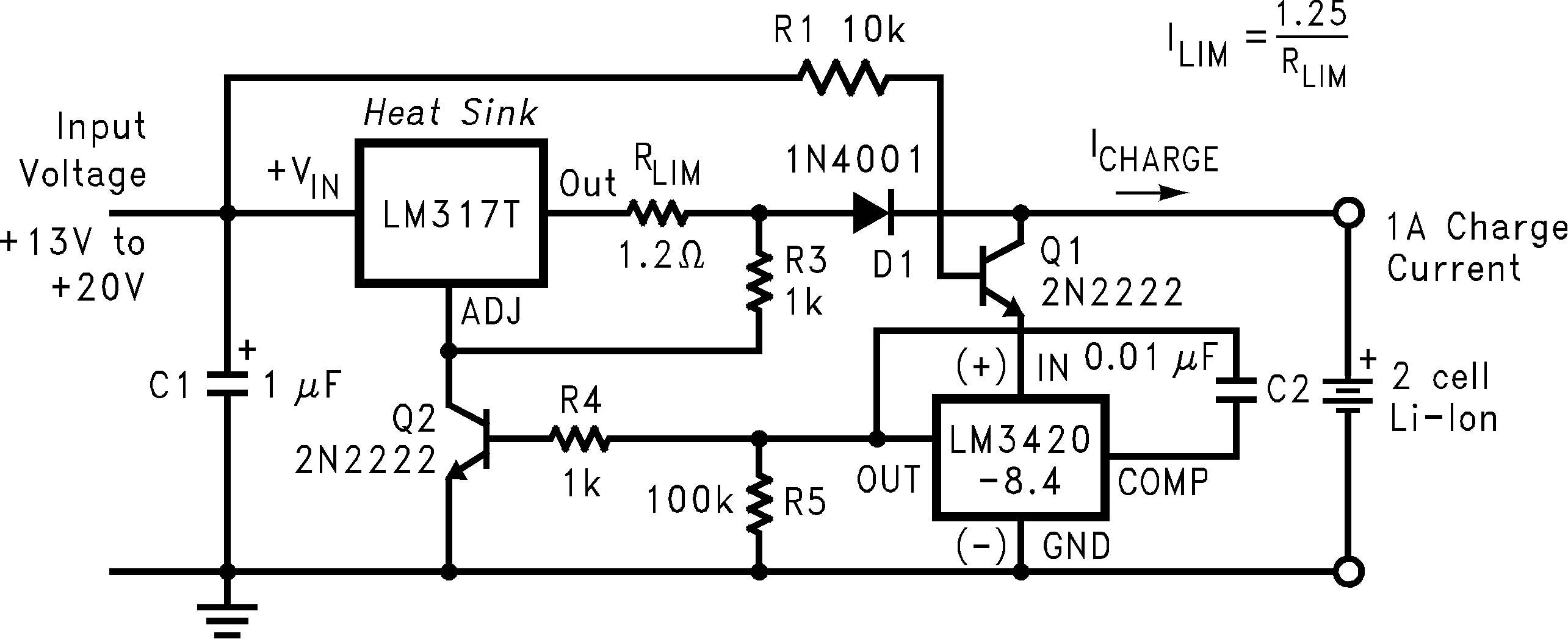
- 9.2.4.1 Low Dropout Constant Current/Constant Voltage 2-Cell Charger
- 9.2.4.2 High-Efficiency Switching Regulator Constant Current/Constant Voltage 2-Cell Charger
- 9.2.4.3 Low Dropout Constant Current/Constant Voltage Li-Ion Battery Charger
- 9.2.4.4 High-Efficiency Switching Charger With High Side Current Sensing
- 9.2.4.5 Fast-Pulsed Constant Current 2-Cell Charger
- 9.2.4.6 MOSFET Low Dropout Charger
- 10Power Supply Recommendations
- 11Layout
- 12Device and Documentation Support
- 13Mechanical, Packaging, and Orderable Information
Package Options
Mechanical Data (Package|Pins)
- DBV|5
Thermal pad, mechanical data (Package|Pins)
Orderable Information
1 Features
- Input Voltage Range: up to 20 V
- Voltage Options for Charging 1, 2, 3, or 4 Cells
- Output Current up to 15 mA
- Precision (0.5%) End-of-Charge Control
- LM3420 ±1%
- LM3420A ±0.5%
- Drive Capability for External Power Stage
- Temperature Drift Curvature Correction for Voltage Stability
- Low Quiescent Current, 85 μA (Typ.)
- Tiny SOT-23-5 package
2 Applications
- Lithium-Ion Battery Charging
- Suitable for Linear and Switching Regulator Charger Designs
3 Description
The LM3420 series of controllers are monolithic integrated circuits designed for charging and end-of-charge control for lithium-ion rechargeable batteries. The LM3420 is available in an 8.4-V version for one through four cell charger applications.
Included in a very small package is an (internally compensated) op amp, a bandgap reference, an NPN output transistor, and voltage setting resistors. The amplifier's inverting input is externally accessible for loop frequency compensation. The output is an open-emitter NPN transistor capable of driving up to 15 mA of output current into external circuitry.
A trimmed precision bandgap reference utilizes temperature drift curvature correction for excellent voltage stability over the operating temperature range. The LM3420 series allows for precision end-of-charge voltage threshold for lithium-ion rechargeable batteries. The premium grade LM3420A is available with an initial voltage threshold tolerance of ±0.5%, while the standard grade LM3420 has an initial voltage threshold tolerance of ±1%.
The LM3420 is available in a sub-miniature 5-lead surface mount package thus allowing very compact designs.
Device Information(1)
| PART NUMBER | PACKAGE | BODY SIZE (NOM) |
|---|---|---|
| LM3420 | SOT-23 (5) | 2.90 mm x 1.60 mm |
- For all available packages, see the orderable addendum at the end of the datasheet.
Simplified Schematic