SNVS116E May 1998 – December 2014 LM3420
PRODUCTION DATA.
- 1 Features
- 2 Applications
- 3 Description
- 4 Revision History
- 5 Pin Configuration and Functions
- 6 Specifications
- 7 Parameter Measurement Information
- 8 Detailed Description
-
9 Application and Implementation
- 9.1 Application Information
- 9.2
Typical Application: Constant Current/Constant Voltage Li-Ion Battery Charger
- 9.2.1 Design Requirements
- 9.2.2 Detailed Design Procedure
- 9.2.3 Application Curve
- 9.2.4
Other Application Circuits
- 9.2.4.1 Low Dropout Constant Current/Constant Voltage 2-Cell Charger
- 9.2.4.2 High-Efficiency Switching Regulator Constant Current/Constant Voltage 2-Cell Charger
- 9.2.4.3 Low Dropout Constant Current/Constant Voltage Li-Ion Battery Charger
- 9.2.4.4 High-Efficiency Switching Charger With High Side Current Sensing
- 9.2.4.5 Fast-Pulsed Constant Current 2-Cell Charger
- 9.2.4.6 MOSFET Low Dropout Charger
- 10Power Supply Recommendations
- 11Layout
- 12Device and Documentation Support
- 13Mechanical, Packaging, and Orderable Information
Package Options
Mechanical Data (Package|Pins)
- DBV|5
Thermal pad, mechanical data (Package|Pins)
Orderable Information
9 Application and Implementation
NOTE
Information in the following applications sections is not part of the TI component specification, and TI does not warrant its accuracy or completeness. TI’s customers are responsible for determining suitability of components for their purposes. Customers should validate and test their design implementation to confirm system functionality.
9.1 Application Information
The LM3420 regulator/driver provides the reference and feedback drive functions for a Lithium-Ion battery charger. It can be used in many different charger configurations using both linear and switching topologies to provide the precision needed for charging lithium-ion batteries safely and efficiently. Output voltage tolerances better than 0.5% are possible without using trim pots or precision resistors. The circuits shown are designed for 2-cell operation, but they can readily be changed for either 1-, 3-, or 4-cell charging applications.
One item to keep in mind when designing with the LM3420 is that there are parasitic diodes present. In some designs, under special electrical conditions, unwanted currents may flow. Parasitic diodes exist from OUT to IN, as well as from GROUND to IN. In both instances the diode arrow is pointed toward the IN pin.
9.2 Typical Application: Constant Current/Constant Voltage Li-Ion Battery Charger
The circuit shown in Figure 14 performs constant-current, constant-voltage charging of two Li-Ion cells. At the beginning of the charge cycle, when the battery voltage is less than 8.4 V, the LM3420 sources no current from the OUT pin, keeping Q2 off, thus allowing the LM317 Adjustable voltage regulator to operate as a constant-current source. (The LM317 is rated for currents up to 1.5 A, and the LM350 and LM338 can be used for higher currents.) The LM317 forces a constant 1.25 V across RLIM, thus generating a constant current of
Transistor Q1 provides a disconnect between the battery and the LM3420 when the input voltage is removed. This prevents the 85-μA quiescent current of the LM3420 from eventually discharging the battery. In this application Q1 is used as a low offset saturated switch, with the majority of the base drive current flowing through the collector and crossing over to the emitter as the battery becomes fully charged. It provides a very low collector to emitter saturation voltage (approximately 5 mV). Diode D1 is also used to prevent the battery current from flowing through the LM317 regulator from the output to the input when the DC input voltage is removed.
As the battery charges, its voltage begins to rise, and is sensed at the IN pin of the LM3420. Once the battery voltage reaches 8.4 V, the LM3420 begins to regulate and starts sourcing current to the base of Q2. Transistor Q2 begins controlling the ADJ pin of the LM317 which begins to regulate the voltage across the battery and the constant voltage portion of the charging cycle starts. Once the charger is in the constant voltage mode, the charger maintains a regulated 8.4 V across the battery and the charging current is dependent on the state of charge of the battery. As the cells approach a fully charged condition, the charge current falls to a very low value.
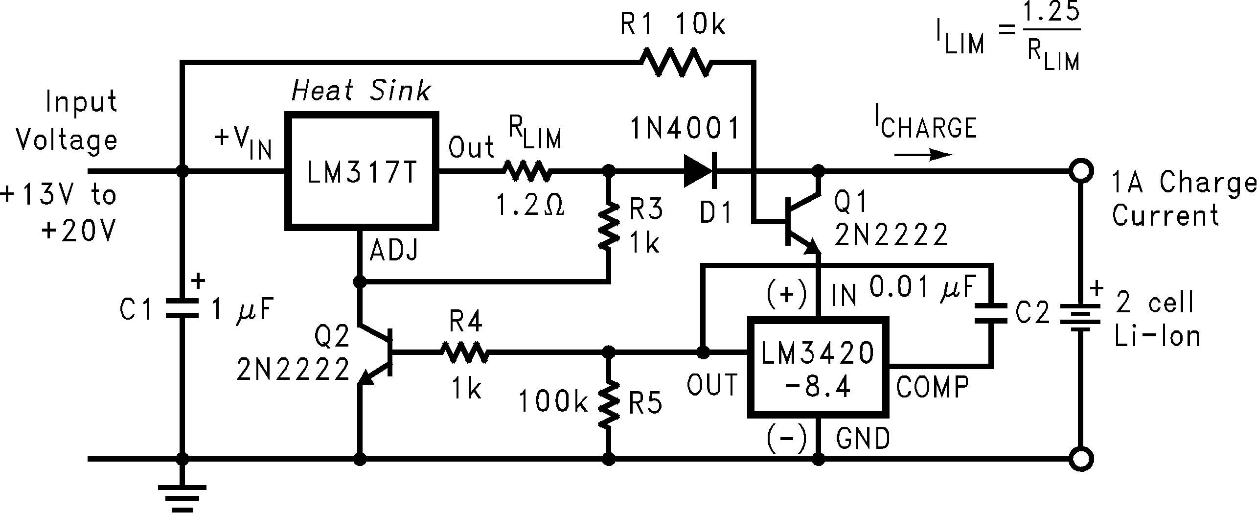 Figure 14. Constant Current/Constant Voltage Li-Ion Battery Charger
9.2.1 Design Requirements
| DESIGN PARAMETER | EXAMPLE VALUE |
|---|---|
| Input voltage | 13 V - 20 V |
| Output voltage | 8.4 V |
| Output current | 1 A |
9.2.2 Detailed Design Procedure
9.2.2.1 Compensation Capacitor
The capacitor between OUT pin and COMP pin can be increase or decreased depending on the desired loop response. Functional Block Diagram can be referred as different capacitance selection. In this case, 0.01-µF capacitor is used.
9.2.3 Application Curve
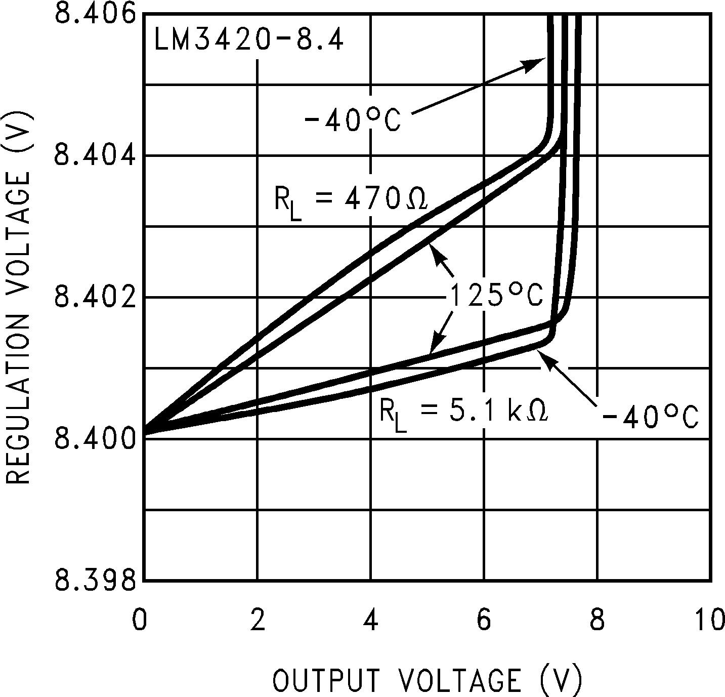 Figure 15. Regulation Voltage vs Output Voltage and Load Resistance
9.2.4 Other Application Circuits
NOTE
Although the application circuits shown here have been built and tested, they should be thoroughly evaluated with the same type of battery the charger will eventually be used with.
Different battery manufacturers may use a slightly different battery chemistry which may require different charging characteristics. Always consult the battery manufacturer for information on charging specifications and battery details, and always observe the manufacturers precautions when using their batteries. Avoid overcharging or shorting Lithium-Ion batteries.
9.2.4.1 Low Dropout Constant Current/Constant Voltage 2-Cell Charger
Figure 16 shows a Li-Ion battery charger that features a dropout voltage of less than one volt. This charger is a constant-current, constant-voltage charger (it operates in constant-current mode at the beginning of the charge cycle and switches over to a constant-voltage mode near the end of the charging cycle). The circuit consists of two basic feedback loops. The first loop controls the constant charge current delivered to the battery, and the second determines the final voltage across the battery.
With a discharged battery connected to the charger, (battery voltage is less than 8.4 V) the circuit begins the charge cycle with a constant charge current. The value of this current is set by using the reference section of the LM10C to force 200 mV across R7 thus causing approximately 100 μA of emitter current to flow through Q1, and approximately 1 mA of emitter current to flow through Q2. The collector current of Q1 is also approximately 100 μA, and this current flows through R2 developing 50 mV across it. This 50 mV is used as a reference to develop the constant charge current through the current sense resistor R1.
The constant current feedback loop operates as follows. Initially, the emitter and collector current of Q2 are both approximately 1 mA, thus providing gate drive to the MOSFET Q3, turning it on. The output of the LM301A op-amp is low. As the Q3 current reaches 1 A, the voltage across R1 approaches 50 mV, thus canceling the 50-mV drop across R2, and causing the op-amp's output to start going positive, and begin sourcing current into R8. As more current is forced into R8 from the op-amp, the collector current of Q2 is reduced by the same amount, which decreases the gate drive to Q3, to maintain a constant 50 mV across the 0.05-Ω current sensing resistor, thus maintaining a constant 1 A of charge current.
The current limit loop is stabilized by compensating the LM301A with C1 (the standard frequency compensation used with this op-amp) and C2, which is additional compensation needed when D3 is forward biased. This helps speed up the response time during the reverse bias of D3. When the LM301A output is low, diode D3 reverse biases and prevents the op-amp from pulling more current through the emitter of Q2. This is important when the battery voltage reaches 8.4 V, and the 1A charge current is no longer needed. Resistor R5 isolates the LM301A feedback node at the emitter of Q2.
The battery voltage is sensed and buffered by the op-amp section of the LM10C, connected as a voltage follower driving the LM3420. When the battery voltage reaches 8.4 V, the LM3420 begins regulating by sourcing current into R8, which controls the collector current of Q2, which in turn reduces the gate voltage of Q3 and becomes a constant voltage regulator for charging the battery. Resistor R6 isolates the LM3420 from the common feedback node at the emitter of Q2. If R5 and R6 are omitted, oscillations could occur during the transition from the constant-current to the constant-voltage mode. D2 and the PNP transistor input stage of the LM10C disconnects the battery from the charger circuit when the input supply voltage is removed to prevent the battery from discharging.
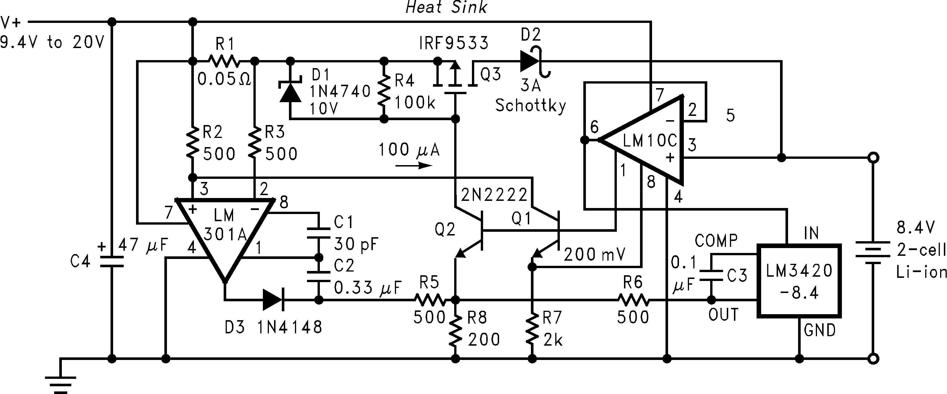 Figure 16. Low Dropout Constant Current/Constant Voltage 2-Cell Charger
9.2.4.2 High-Efficiency Switching Regulator Constant Current/Constant Voltage 2-Cell Charger
A switching regulator, constant-current, constant-voltage two-cell Li-Ion battery charging circuit is shown in Figure 17. This circuit provides much better efficiency, especially over a wide input voltage range than the linear topologies. For a 1-A charger an LM2575-ADJ. switching regulator IC is used in a standard buck topology. For other currents, or other packages, other members of the SIMPLE SWITCHER® buck regulator family may be used.
Circuit operation is as follows. With a discharged battery connected to the charger, the circuit operates as a constant current source. The constant-current portion of the charger is formed by the loop consisting of one half of the LM358 op amp along with gain setting resistors R3 and R4, current sensing resistor R5, and the feedback reference voltage of 1.23 V. Initially the LM358 output is low causing the output of the LM2575-ADJ to rise thus causing some charging current to flow into the battery. When the current reaches 1 A, it is sensed by resistor R5 (50 mΩ), and produces 50 mV. This 50 mV is amplified by the op-amps gain of 25 to produce 1.23V, which is applied to the feedback pin of the LM2575-ADJ to satisfy the feedback loop.
Once the battery voltage reaches 8.4 V, the LM3420 takes over and begins to control the feedback pin of the LM2575-ADJ. The LM3420 now regulates the voltage across the battery, and the charger becomes a constant-voltage charger. Loop compensation network R6 and C3 ensure stable operation of the charger circuit under both constant-current and constant-voltage conditions. If the input supply voltage is removed, diode D2 and the PNP input stage of the LM358 become reversed biased and disconnects the battery to ensure that the battery is not discharged. Diode D3 reverse biases to prevent the op-amp from sinking current when the charger changes to constant voltage mode.
The minimum supply voltage for this charger is approximately 11 V, and the maximum is around 30 V (limited by the 32-V maximum operating voltage of the LM358). If another op-amp is substituted for the LM358, make sure that the input common-mode range of the op-amp extends down to ground so that it can accurately sense 50 mV. R1 is included to provide a minimum load for the switching regulator to assure that switch leakage current does not cause the output to rise when the battery is removed.
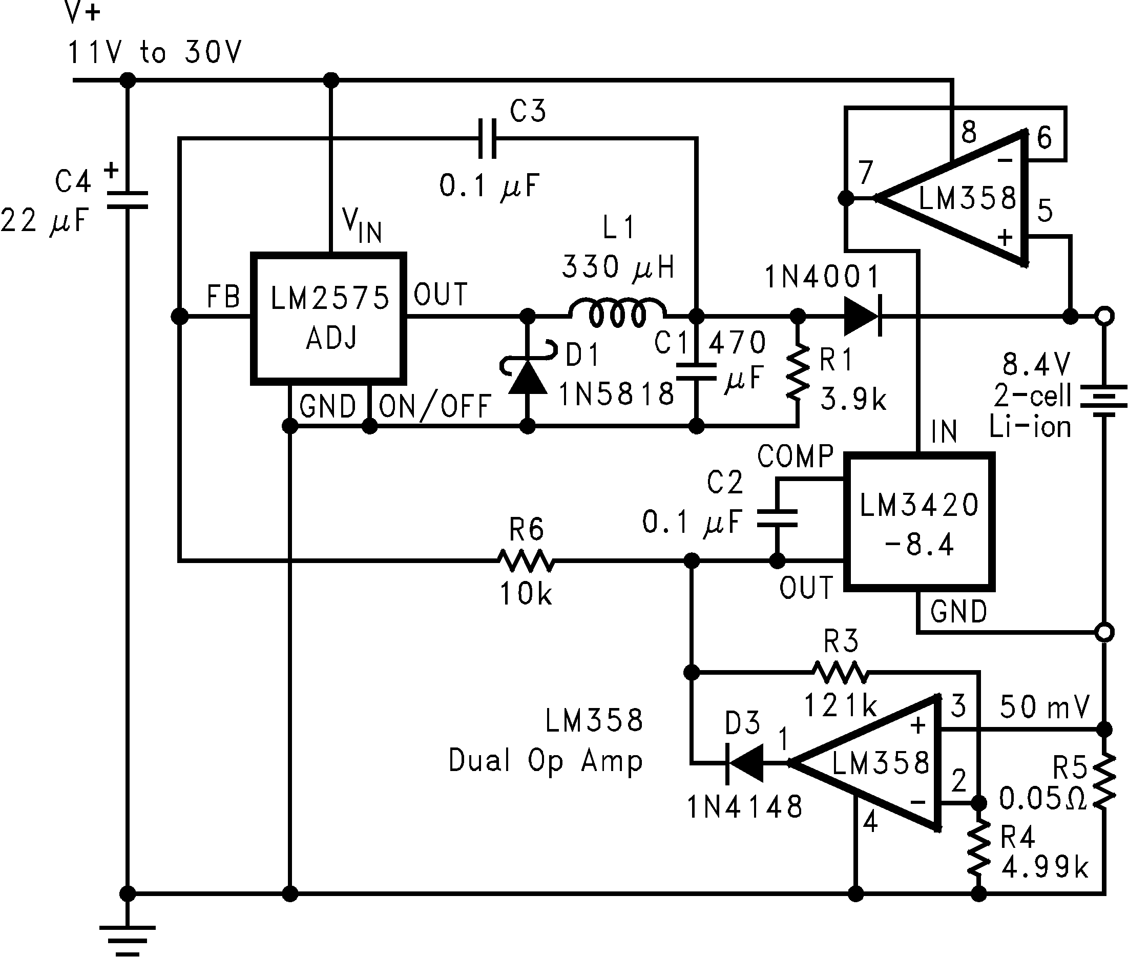 Figure 17. High-Efficiency Switching Regulator Constant Current/Constant Voltage 2-Cell Charger
9.2.4.3 Low Dropout Constant Current/Constant Voltage Li-Ion Battery Charger
The circuit in Figure 18 is very similar to Figure 17, except the switching regulator has been replaced with a low dropout linear regulator, allowing the input voltage to be as low as 10 V. The constant current and constant voltage control loops are the same as the previous circuit. Diode D2 has been changed to a Schottky diode to provide a reduction in the overall dropout voltage of this circuit, but Schottky diodes typically have higher leakage currents than a standard silicon diode. This leakage current could discharge the battery if the input voltage is removed for an extended period of time.
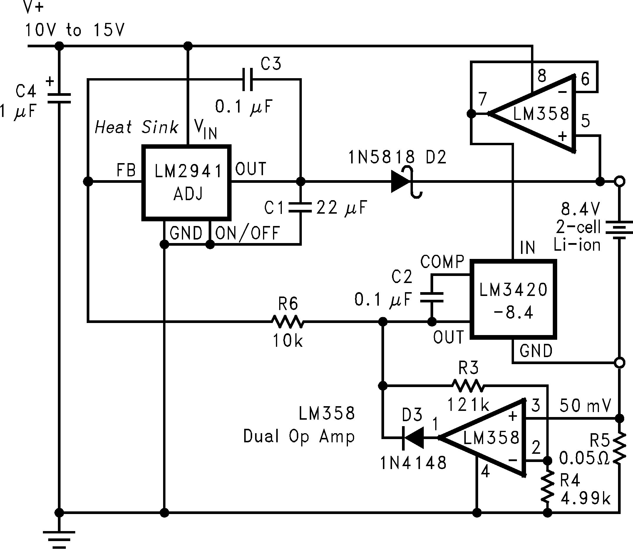 Figure 18. Low Dropout Constant Current/Constant Voltage Li-Ion Battery Charger
9.2.4.4 High-Efficiency Switching Charger With High Side Current Sensing
Another variation of a constant current/constant voltage switch mode charger is shown in Figure 19. The basic feedback loops for current and voltage are similar to the previous circuits. This circuit has the current sensing resistor, for the constant current part of the feedback loop, on the positive side of the battery, thus allowing a common ground between the input supply and the battery. Also, the LMC7101 op-amp is available in a very small SOT-23-5 package thus allowing a very compact PC board design. Diode D4 prevents the battery from discharging through the charger circuitry if the input voltage is removed, although the quiescent current of the LM3420 is still present (approximately 85 μA).
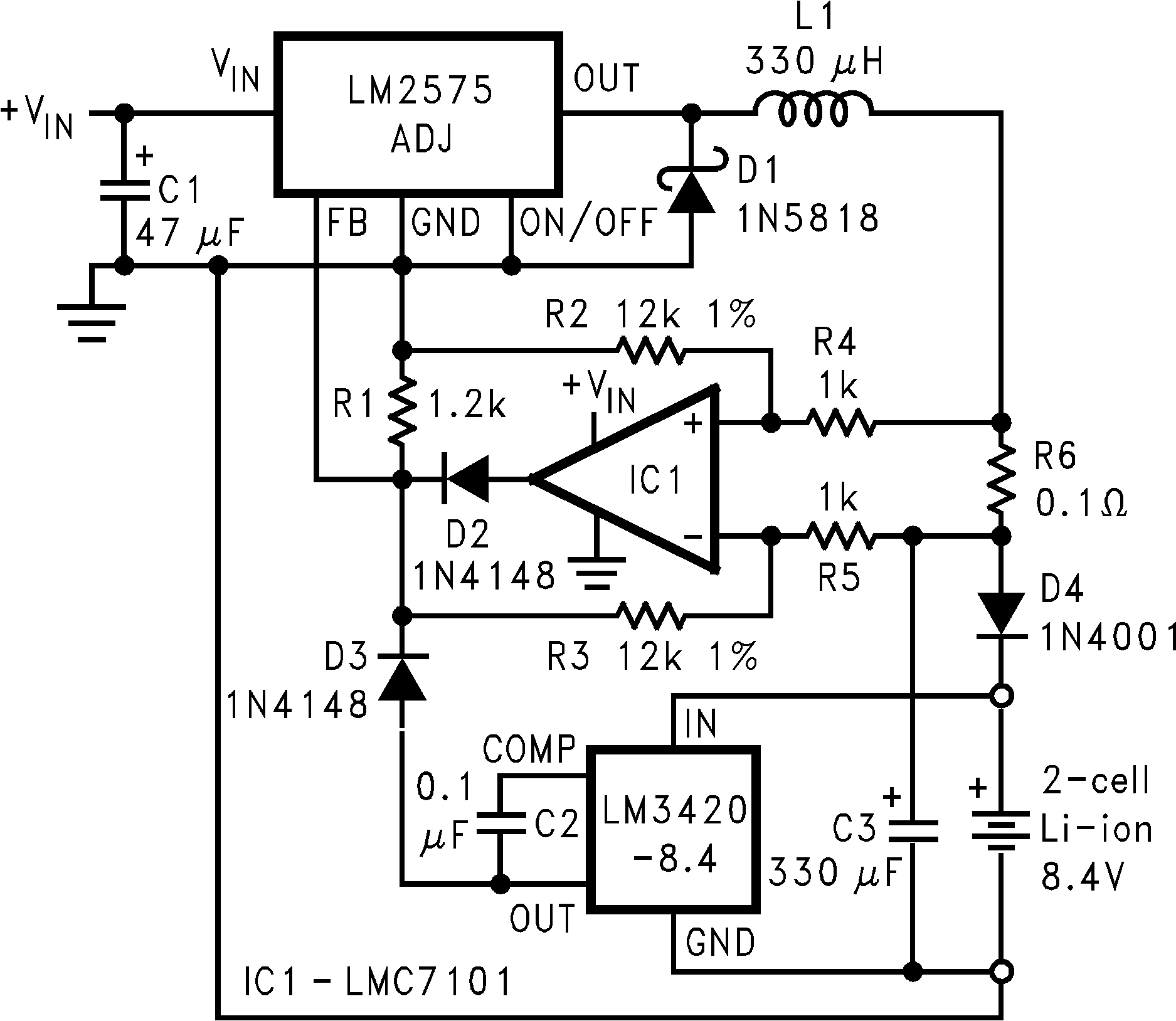 Figure 19. High Efficiency Switching Charger
With High Side Current Sensing
9.2.4.5 Fast-Pulsed Constant Current 2-Cell Charger
A rapid charge Lithium-Ion battery charging circuit is shown in Figure 20. This configuration uses a switching regulator to deliver the charging current in a series of constant current pulses. At the beginning of the charge cycle (constant-current mode), this circuit performs identically to the previous LM2575 charger by charging the battery at a constant current of 1 A. As the battery voltage reaches 8.4 V, this charger changes from a constant continuous current of 1 A to a 5-second pulsed 1 A. This allows the total battery charge time to be reduced considerably. This is different from the other charging circuits that switch from a constant current charge to a constant voltage charge once the battery voltage reaches 8.4 V. After charging the battery with 1 A for 5 seconds, the charge stops, and the battery voltage begins to drop. When it drops below 8.4 V, the LM555 timer again starts the timing cycle and charges the battery with 1 A for another 5 seconds. This cycling continues with a constant 5-second charge time, and a variable off time. In this manner, the battery is charged with 1 A for 5 seconds, followed by an off period (determined by the battery's state of charge), setting up a periodic 1-A charge current. The off time is determined by how long it takes the battery voltage to decrease back down to 8.4 V. When the battery first reaches 8.4 V, the off time is very short (1 ms or less), but when the battery approaches full charge, the off time begins increasing to tens of seconds, then minutes, and eventually hours.
The constant-current loop for this charger and the method used for programming the 1-A constant current is identical to the previous LM2575-ADJ charger. In this circuit, a second LM3420-8.4 has its VREG increased by approximately 400 mV (via R2), and is used to limit the output voltage of the charger to 8.8V in the event of a bad battery connection, or the battery is removed or possibly damaged.
The LM555 timer is connected as a one-shot, and is used to provide the 5-second charging pulses. As long as the battery voltage is less than the 8.4 V, the output of IC3 is held low, and the LM555 one-shot never fires (the output of the LM555 is held high) and the one-shot has no effect on the charger. Once the battery voltage exceeds the 8.4-V regulation voltage of IC3, the trigger pin of the LM555 is pulled high, enabling the one shot to begin timing. The charge current is now pulsed into the battery at a 5-second rate, with the off time determined by the battery's state of charge. The LM555 output goes high for 5 seconds (pulling down the collector of Q1) which allows the 1-A constant-current loop to control the circuit.
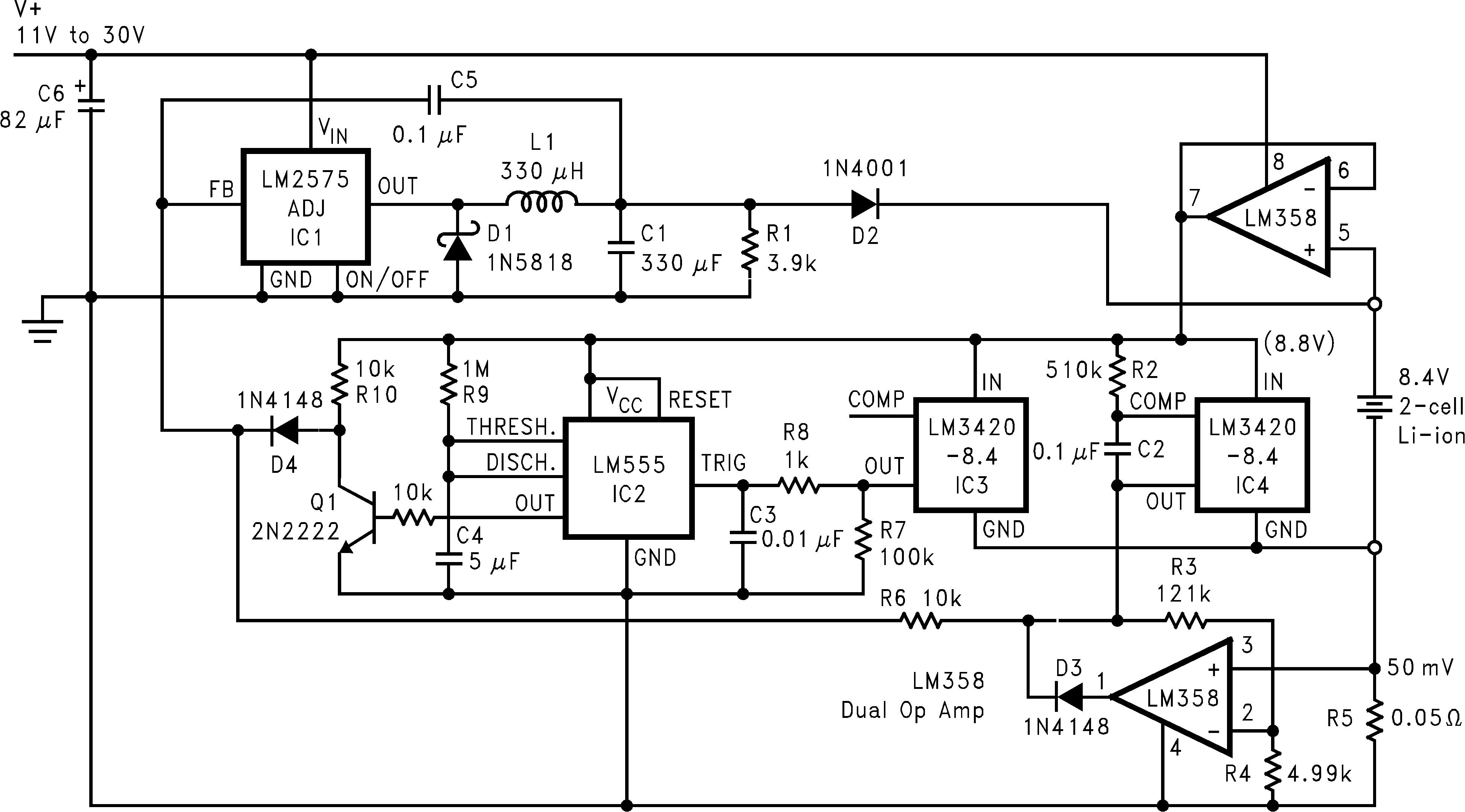 Figure 20. (Fast) Pulsed Constant Current 2-Cell Charger
9.2.4.6 MOSFET Low Dropout Charger
Figure 21 shows a low dropout constant voltage charger using a MOSFET as the pass element, but this circuit does not include current limiting. This circuit uses Q3 and a Schottky diode to isolate the battery from the charging circuitry when the input voltage is removed, to prevent the battery from discharging. Q2 should be a high-current (0.2-Ω) FET, while Q3 can be a low-current (2-Ω) device.
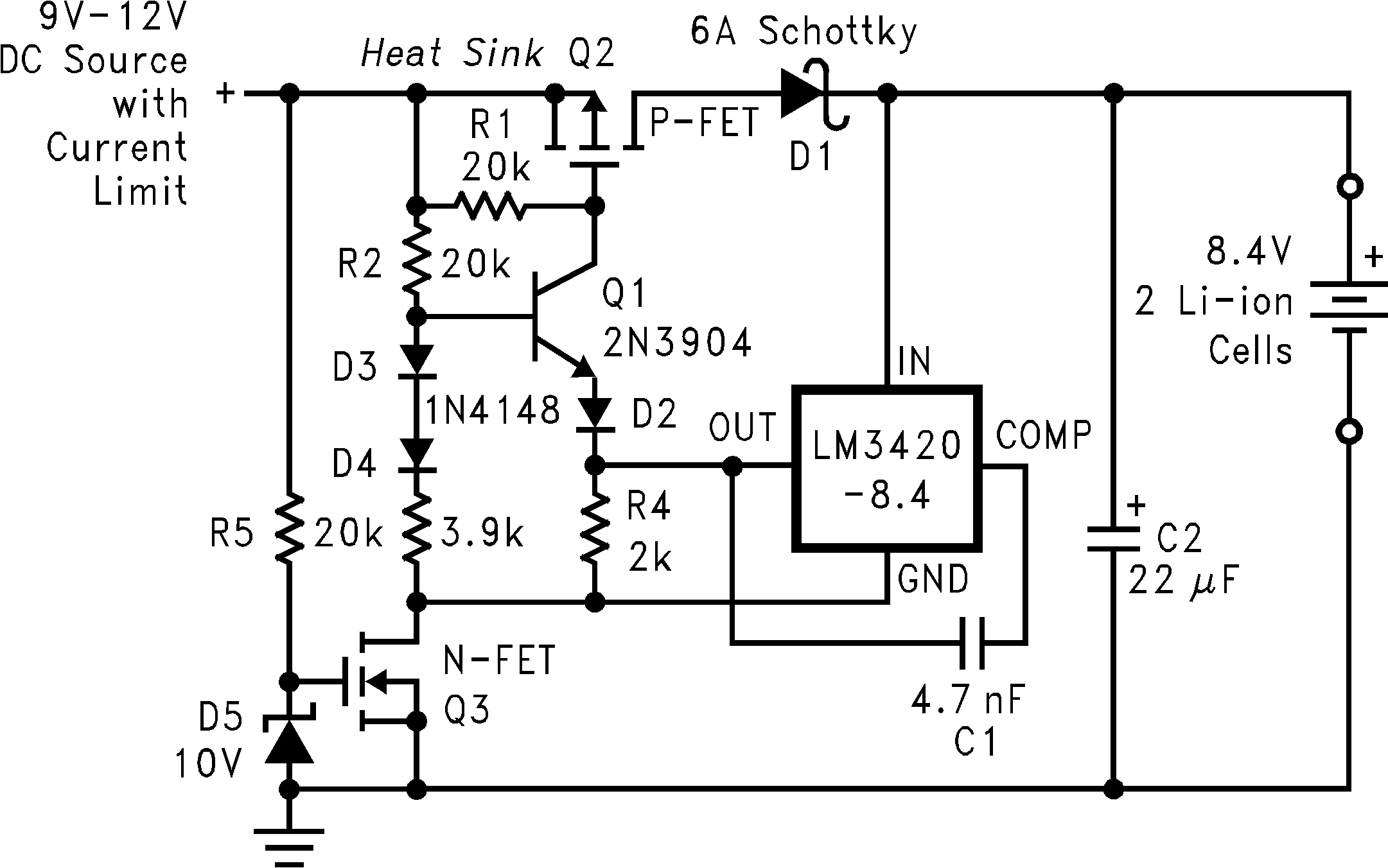 Figure 21. MOSFET Low Dropout Charger