SNVS667I February   2010  – March 2022 LMZ12010

PRODUCTION DATA  

  1. Features
  2. Applications
  3. Description
  4. Revision History
  5. Pin Configuration and Functions
  6. Specifications
    1. 6.1 Absolute Maximum Ratings
    2. 6.2 ESD Ratings
    3. 6.3 Recommended Operating Conditions
    4. 6.4 Thermal Information
    5. 6.5 Electrical Characteristics
    6. 6.6 Typical Characteristics
  7. Detailed Description
    1. 7.1 Overview
    2. 7.2 Functional Block Diagram
    3. 7.3 Feature Description
      1. 7.3.1 Output Overvoltage Protection
      2. 7.3.2 Current Limit
      3. 7.3.3 Thermal Protection
      4. 7.3.4 Prebiased Start-Up
    4. 7.4 Device Functional Modes
      1. 7.4.1 Discontinuous Conduction and Continuous Conduction Modes
  8. Application and Implementation
    1. 8.1 Application Information
    2. 8.2 Typical Application
      1. 8.2.1 Design Requirements
      2. 8.2.2 Detailed Design Procedure
        1. 8.2.2.1 Enable Divider, RENT, RENB, and RENH Selection
        2. 8.2.2.2 Output Voltage Selection
        3. 8.2.2.3 Soft-Start Capacitor Selection
        4. 8.2.2.4 Tracking Supply Divider Option
        5. 8.2.2.5 COUT Selection
        6. 8.2.2.6 CIN Selection
      3. 8.2.3 Application Curves
  9. Power Supply Recommendations
  10. 10Layout
    1. 10.1 Layout Guidelines
    2. 10.2 Layout Examples
    3. 10.3 Power Dissipation and Thermal Considerations
    4. 10.4 Power Module SMT Guidelines
  11. 11Device and Documentation Support
    1. 11.1 Device Support
      1. 11.1.1 Third-Party Products Disclaimer
      2. 11.1.2 Development Support
    2. 11.2 Documentation Support
      1. 11.2.1 Related Documentation
    3. 11.3 Support Resources
    4. 11.4 Receiving Notification of Documentation Updates
    5. 11.5 Trademarks
    6. 11.6 Electrostatic Discharge Caution
    7. 11.7 Glossary
  12. 12Mechanical, Packaging, and Orderable Information

Package Options

Mechanical Data (Package|Pins)
Thermal pad, mechanical data (Package|Pins)
Orderable Information

Prebiased Start-Up

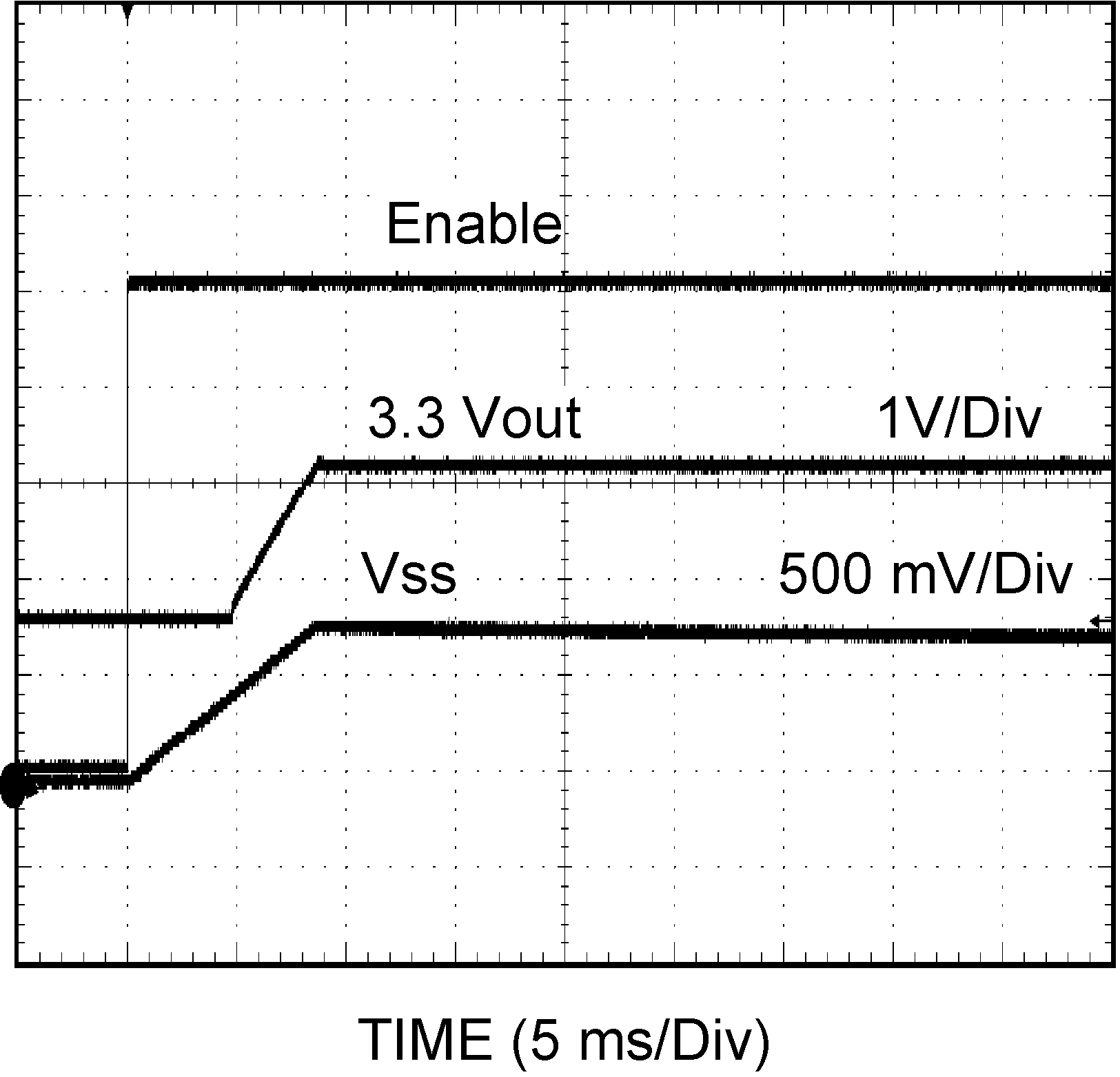
The LMZ12010 will properly start up into a prebiased output. This start-up situation is common in multiple rail logic applications where current paths can exist between different power rails during the start-up sequence. Figure 7-1 shows proper behavior in this mode. Trace one is Enable going high. Trace two is 1.8-V prebias rising to 3.3 V. Trace three is the SS voltage with a CSS = 0.47 µF. Rise time is determined by CSS.
GUID-C5D464CC-3800-4C16-9213-14AA78144AF9-low.pngFigure 7-1 Prebiased Start-Up