SBOS566C June 2017 – October 2018 OPA1692
PRODUCTION DATA.
- 1 Features
- 2 Applications
- 3 Description
- 4 Revision History
- 5 Pin Configuration and Functions
- 6 Specifications
- 7 Detailed Description
- 8 Application and Implementation
- 9 Power Supply Recommendations
- 10Layout
- 11Device and Documentation Support
- 12Mechanical, Packaging, and Orderable Information
Package Options
Mechanical Data (Package|Pins)
Thermal pad, mechanical data (Package|Pins)
Orderable Information
8.2.3 Application Curves
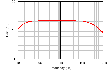
Table 3 lists the performance of the preamplifier circuit in Figure 60. The total power supply current of the circuit is a combination of the 600 µA consumed by the microphone element itself and the 650 µA power-supply current of the OPA1692. Figure 61 shows the frequency response of the circuit. Comparing the output signal level of the microphone for a 1-Pa input signal level to the A-weighted noise of the preamplifier circuit and microphone determines the SNR of the circuit. For a 1-Pa input sound level, the microphone produces a 14.13 mVRMS signal. The microphone has an SNR of 80 dB, which results in a RMS noise voltage of 1.41 µVRMS. The input-referred A-weighted noise voltage of the preamplifier circuit is 600.6 nVRMS. The microphone and preamplifier noise must be combined as a root sum of squares, which results in a total RMS noise voltage of 1.53 µVRMS and a total circuit SNR of 79.3 dB. By selecting the OPA1692 for this design, this circuit achieves a high level of performance with low power consumption.
Table 3. Comparison of Design Requirements and Results
| SPECIFICATION | DESIGN REQUIREMENT | DESIGN RESULT |
|---|---|---|
| Gain | 12 V/V or 21.6 dB (120 dB Maximum Input SPL) | 11.79 V/V or 21.43 dB |
| –3-dB bandwidth | 20 Hz to 20 kHz | 24 Hz to 21 kHz |
| Signal-to-noise ratio | > 75 dB | 79.3 dB |
| Power supply current (microphone and amplifier circuit) | < 1.5 mA | 1.25 mA |
 Figure 61. Frequency Response of the Low-Noise Preamplifier for 3-Wire Electret Microphones