SCPS270B August   2020  – November 2023 TCA4307

PRODUCTION DATA  

  1.   1
  2. Features
  3. Applications
  4. Description
  5. Pin Configuration and Functions
  6. Specifications
    1. 5.1 Absolute Maximum Ratings
    2. 5.2 ESD Ratings
    3. 5.3 Recommended Operating Conditions
    4. 5.4 Thermal Information
    5. 5.5 Electrical Characteristics
    6. 5.6 Timing Requirements
    7. 5.7 Switching Characteristics
  7. Parameter Measurement Information
  8. Detailed Description
    1. 7.1 Overview
    2. 7.2 Functional Block Diagram
    3. 7.3 Feature Description
      1. 7.3.1 Hot bus insertion
      2. 7.3.2 Pre-charge voltage
      3. 7.3.3 Rise time accelerators
      4. 7.3.4 Bus ready output indicator
      5. 7.3.5 Powered-off high impedance for I2C and I/O pins
      6. 7.3.6 Supports clock stretching and arbitration
      7. 7.3.7 Stuck bus recovery
    4. 7.4 Device Functional Modes
      1. 7.4.1 Start-up and precharge
      2. 7.4.2 Bus idle
      3. 7.4.3 Bus active
      4. 7.4.4 Bus stuck
  9. Application and Implementation
    1. 8.1 Application Information
    2. 8.2 Typical Application
      1. 8.2.1 Design Requirements
        1. 8.2.1.1 Series connections
        2. 8.2.1.2 Multiple connections to a common node
        3. 8.2.1.3 Propagation delays
      2. 8.2.2 Detailed Design Procedure
      3. 8.2.3 Application Curves
      4. 8.2.4 Typical Application on a Backplane
        1. 8.2.4.1 Design Requirements
        2. 8.2.4.2 Detailed Design Procedure
    3. 8.3 Power Supply Recommendations
      1. 8.3.1 Power Supply Best Practices
      2. 8.3.2 Power-on Reset Requirements
    4. 8.4 Layout
      1. 8.4.1 Layout Guidelines
      2. 8.4.2 Layout Example
  10. Device and Documentation Support
    1. 9.1 Receiving Notification of Documentation Updates
    2. 9.2 Support Resources
    3. 9.3 Trademarks
    4. 9.4 Electrostatic Discharge Caution
    5. 9.5 Glossary
  11. 10Revision History
  12. 11Mechanical, Packaging, and Orderable Information

Package Options

Mechanical Data (Package|Pins)
Thermal pad, mechanical data (Package|Pins)
Orderable Information

Typical Application on a Backplane

As shown in Figure 8-6, the TCA4307 is used in a backplane connection. The TCA4307 is placed on the I/O peripheral card and connects the I2C devices on the card to the backplane safely upon a hot insertion event. Note that if the I/O cards were plugged directly into the backplane, all of the backplane and card capacitances would add directly together, making rise time and fall time requirements difficult to meet. Placing a bus buffer on the edge of each card; however, isolates the card capacitance from the backplane. For a given I/O card, the TCA4307 drives the capacitance of everything on the card and the backplane must drive only the capacitance of the bus buffer, which is less than 10 pF, the connector, trace, and all additional cards on the backplane.
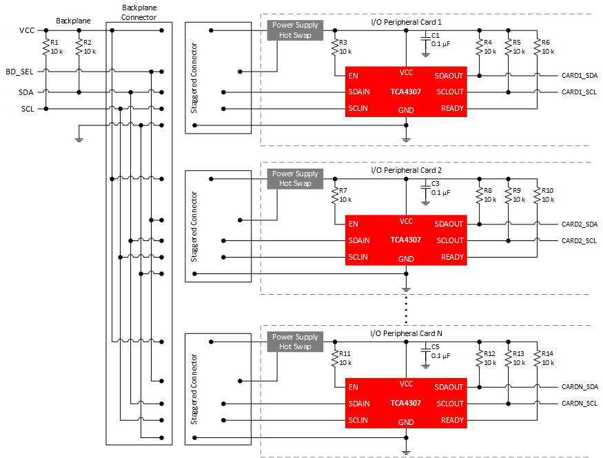
GUID-A5A67F7C-2B2B-4383-AE1F-6EDFDFEFD2CF-low.gif Figure 8-6 Backplane Application Schematic