SLVS850A June 2008 – September 2023 TPS2551-Q1
PRODUCTION DATA
- 1
- 1 Features
- 2 Applications
- 3 Description
- 4 Revision History
- 5 Pin Configurations and Functions
- 6 Specifications
- 7 Parameter Measurement Information
- 8 Detailed Description
- 9 Application and Implementation
- 10Device and Documentation Support
- 11Mechanical, Packaging, and Orderable Information
Package Options
Mechanical Data (Package|Pins)
- DBV|6
Thermal pad, mechanical data (Package|Pins)
Orderable Information
8.4.1 Programming the Current-Limit Threshold
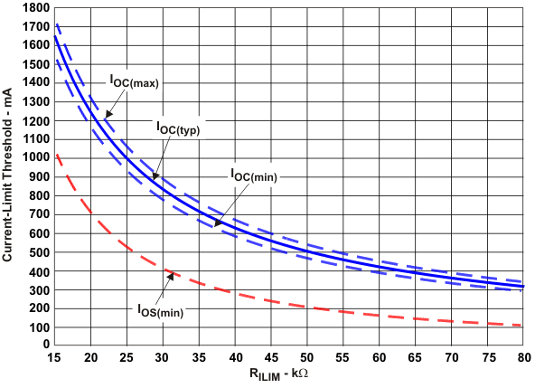
The overcurrent threshold is user programmable via an external resistor. Many applications require that the minimum current-limit is above a certain current level or that the maximum current-limit is below a certain current level, so it is important to consider the tolerance of the overcurrent threshold when selecting a value for RILIM. The following equations and Figure 8-1 can be used to calculate the resulting overcurrent threshold for a given external resistor value (RILIM). Figure 8-1 includes current-limit tolerance due to variations caused by temperature and process. Ensure that the traces routing the RILIM resistor to the TPS2551 are as short as possible to reduce parasitic effects on the current-limit accuracy.
There are two important current-limit thresholds for the device and are related by Figure 7-3. The first threshold is the short-circuit current threshold IOS. IOS is the current delivered to the load if the part is enabled into a short-circuit or a short-circuit is applied during normal operation. The second threshold is the overcurrent threshold IOC. IOC is the peak dc current that can be delivered to the load before the device begins to limit current. IOC is important if ramped loads or slow transients are common to the application. It is important to consider both IOS and IOC when choosing RILIM. RILIM can be selected to provide a current-limit threshold that occurs 1) above a minimum load current or 2) below a maximum load current.
To design above a minimum current-limit threshold, find the intersection of RILIM and the maximum desired load current on the IOS(min) curve and choose a value of RILIM below this value. Programming the current-limit above a minimum threshold is important to ensure start-up into full-load or heavy capacitive loads. The resulting maximum dc load current is the intersection of the selected value of RILIM and the IOC(max) curve.
To design below a maximum dc current level, find the intersection of RILIM and the maximum desired load current on the IOC(max) curve and choose a value of RILIM above this value. Programming the current-limit below a maximum threshold is important to avoid current-limiting upstream power supplies causing the input voltage bus to droop. The resulting minimum short-circuit current is the intersection of the selected value of RILIM and the IOS(min) curve.
Overcurrent threshold equations (IOC):
- IOC(max) (mA) = (24500 V) / (RILIM kΩ) 0.975 + 50
- IOC(typ) (mA) = (23800 V) / (RILIM kΩ) 0.985 + 50
- IOC(min) (mA) = (23100 V) / (RILIM kΩ) 0.996 + 50
Short-circuit current equations (IOS):
- IOS(max) (mA) = (25500 V) / (RILIM kΩ) 1.013 + 50
- IOS(typ) (mA) = (28700 V) / (RILIM kΩ) 1.114 + 50
- IOS(min) (mA) = (39700 V) / (RILIM kΩ) 1.342 + 50
where 14.3 kΩ ≤ RILIM ≤ 80.6 kΩ. IOS(typ) and IOS(max) are not plotted to improve graph clarity.
 Figure 8-1 Current-Limit Threshold vs RILIM