SLVSEI3C October 2018 – May 2020 TPS25982
PRODUCTION DATA.
- 1 Features
- 2 Applications
- 3 Description
- 4 Revision History
- 5 Device Comparison Table
- 6 Pin Configuration and Functions
- 7 Specifications
-
8 Detailed Description
- 8.1 Overview
- 8.2 Functional Block Diagram
- 8.3 Feature Description
- 8.4 Fault Response
- 8.5 Device Functional Modes
-
9 Application and Implementation
- 9.1 Application Information
- 9.2
Typical Application: Standby Power Rail Protection in Datacenter Servers
- 9.2.1 Design Requirements
- 9.2.2
Detailed Design Procedure
- 9.2.2.1 Device Selection
- 9.2.2.2 Setting the Current Limit Threshold: RILIM Selection
- 9.2.2.3 Setting the Undervoltage Lockout Set Point
- 9.2.2.4 Choosing the Current Monitoring Resistor: RIMON
- 9.2.2.5 Setting the Output Voltage Ramp Time (TdVdt)
- 9.2.2.6 Setting the Load Handshake (LDSTRT) Delay
- 9.2.2.7 Setting the Transient Overcurrent Blanking Interval (tITIMER)
- 9.2.2.8 Setting the Auto-Retry Delay and Number of Retries
- 9.2.3 Application Curves
- 9.3 System Examples
- 10Power Supply Recommendations
- 11Layout
- 12Device and Documentation Support
- 13Mechanical, Packaging, and Orderable Information
Package Options
Mechanical Data (Package|Pins)
- RGE|24
Thermal pad, mechanical data (Package|Pins)
- RGE|24
Orderable Information
3 Description
The TPS25982 family of eFuses is a highly integrated circuit protection and power management solution in a small package. The devices are operational over a wide input voltage range. A single part caters to low-voltage systems needing minimal I*R voltage drop as well as higher voltage, high current systems needing low power dissipation. They are a robust defense against overloads, short-circuits, voltage surges and excessive inrush current.
Overvoltage events are limited by internal cutoff circuits, with multiple device options to choose the overvoltage threshold.
Multiple device options exist to choose between the response to overcurrent conditions, circuit breaker or active current limiter. The overcurrent limit and fast-trip (short-circuit) threshold can be set with a single external resistor. The devices intelligently manage the overcurrent response by distinguishing between transient events and actual faults, thereby allowing the system to function uninterrupted during line and load transients without compromising on the robustness of the protection against faults. The device can be configured to stay latched off or retry automatically after a fault shutdown. The number of auto-retries as well as the retry delay are configurable with capacitors. This enables remote systems to automatically recover from temporary faults while ensuring that power supplies are not stressed indefinitely due to a persistent fault.
The TPS25982 devices are available in a small 4 mm × 4 mm QFN package. The devices are characterized for operation over a junction temperature range of –40˚C to 125˚C.
Device Information(1)
| PART NUMBER | PACKAGE | BODY SIZE (NOM) |
|---|---|---|
| TPS25982 | QFN (24) | 4.0 mm × 4.0 mm |
- For all available packages, see the orderable addendum at the end of the data sheet.
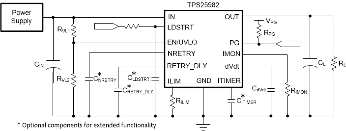
Simplified Schematics
