JAJSDA0 June 2017 DRV10983-Q1
PRODUCTION DATA.
- 1 特長
- 2 アプリケーション
- 3 概要
- 4 改訂履歴
- 5 Description (Continued)
- 6 Pin Configuration and Functions
- 7 Specifications
-
8 Detailed Description
- 8.1 Overview
- 8.2 Functional Block Diagram
- 8.3 Feature Description
- 8.4
Device Functional Modes
- 8.4.1 Motor Parameters
- 8.4.2 Starting the Motor Under Different Initial Conditions
- 8.4.3 Motor Start Sequence
- 8.4.4 Align Current
- 8.4.5 Start-Up Current Setting
- 8.4.6 Closed Loop
- 8.4.7 Current Limit
- 8.4.8 Lock Detect and Fault Handling
- 8.4.9 Anti Voltage Supression Function
- 8.4.10 PWM Output
- 8.4.11 FG Customized Configuration
- 8.4.12
Diagnostics and Visibility
- 8.4.12.1 Motor-Status Readback
- 8.4.12.2 Motor-Speed Readback
- 8.4.12.3 Motor Electrical-Period Readback
- 8.4.12.4 Motor Velocity Constant Read Back
- 8.4.12.5 Motor Estimated Position by IPD
- 8.4.12.6 Supply-Voltage Readback
- 8.4.12.7 Speed-Command Readback
- 8.4.12.8 Speed-Command Buffer Readback
- 8.4.12.9 Fault Diagnostics
- 8.5
Register Maps
- 8.5.1 I2C Serial Interface
- 8.5.2 Register Map
- 8.5.3
Register Descriptions
- 8.5.3.1 FaultReg Register (address = 0x00) [reset = 0x00]
- 8.5.3.2 MotorSpeed Register (address = 0x01) [reset = 0x00]
- 8.5.3.3 MotorPeriod Register (address = 0x02) [reset = 0x00]
- 8.5.3.4 MotorKt Register (address = 0x03) [reset = 0x00]
- 8.5.3.5 MotorCurrent Register (address = 0x04) [reset = 0x00]
- 8.5.3.6 IPDPosition-SupplyVoltage Register (address = 0x05) [reset = 0x00]
- 8.5.3.7 SpeedCmd-spdCmdBuffer Register (address = 0x06) [reset = 0x00]
- 8.5.3.8 AnalogInLvl Register (address = 0x07) [reset = 0x00]
- 8.5.3.9 DeviceID-RevisionID Register (address = 0x08) [reset = 0x00]
- 8.5.3.10 DeviceID-RevisionID Register (address = 0x08) [reset = 0x00]
- 8.5.3.11 Unused Registers (addresses = 0x011 Through 0x2F)
- 8.5.3.12 SpeedCtrl Register (address = 0x30) [reset = 0x00]
- 8.5.3.13 EEPROM Programming1 Register (address = 0x31) [reset = 0x00]
- 8.5.3.14 EEPROM Programming2 Register (address = 0x32) [reset = 0x00]
- 8.5.3.15 EEPROM Programming3 Register (address = 0x33) [reset = 0x00]
- 8.5.3.16 EEPROM Programming4 Register (address = 0x34) [reset = 0x00]
- 8.5.3.17 EEPROM Programming5 Register (address = 0xYY) [reset = 0x00]
- 8.5.3.18 EEPROM Programming6 Register (address = 0x36) [reset = 0x00]
- 8.5.3.19 Unused Registers (addresses = 0x37 Through 0x5F)
- 8.5.3.20 EECTRL Register (address = 0x60) [reset = 0x00]
- 8.5.3.21 Unused Registers (addresses = 0x61 Through 0x8F)
- 8.5.3.22 CONFIG1 Register (address = 0x90) [reset = 0x00]
- 8.5.3.23 CONFIG2 Register (address = 0x91) [reset = 0x00]
- 8.5.3.24 CONFIG3 Register (address = 0x92) [reset = 0x00]
- 8.5.3.25 CONFIG4 Register (address = 0x93) [reset = 0x00]
- 8.5.3.26 CONFIG5 Register (address = 0x94) [reset = 0x00]
- 8.5.3.27 CONFIG6 Register (address = 0x95) [reset = 0x00]
- 8.5.3.28 CONFIG7 Register (address = 0x96) [reset = 0x00]
- 9 Application and Implementation
- 10Power Supply Recommendations
- 11Layout
- 12デバイスおよびドキュメントのサポート
- 13メカニカル、パッケージ、および注文情報
1 特長
- 車載アプリケーションに対応
- 下記内容でAEC-Q100認定済み:
- デバイス温度グレード1: 動作時周囲温度範囲-40°C~125°C
- デバイスHBM ESD分類レベル1C
- デバイスCDM ESD分類レベルC4A
- 動作電圧範囲:
- モータ動作: 6.2V~28V
- レジスタ設定保存: 4.5V~45V
- 最高45Vの負荷ダンプ電圧をサポート
- 合計ドライバH + L rDS(on)
- TA = 25℃で250mΩ
- TA = 125℃で325mΩ
- ドライバ電流: 連続巻線電流2A (ピーク3A)
- EMI管理のため出力PWMスルー・レートと周波数を変更可能
- センサレスの独自の逆起電力(BEMF)制御方式(ホール・センサ不要)
- 連続正弦180°整流
- 初期位置検出アルゴリズムによりスタートアップ時のバック・スピンを防止
- 外部検出抵抗不要
- 柔軟なユーザー・インターフェイス・オプション
- I2Cインターフェイス: コマンドおよびフィードバックのためレジスタにアクセス
- 専用SPEEDピン: アナログまたはPWM入力に対応
- 専用FGピン: TACHフィードバックに使用
- スピンアップ・プロファイルをEEPROMでカスタマイズ可能
- DIRピンによる順方向-逆方向制御
- 内蔵の降圧コンバータにより、内部および外部の回路に5Vおよび3.3V LDOを効率的に供給
- スタンバイ・バージョンでの電源電流8.5mA (DRV10983SQ)
- スリープ・バージョンでの電源電流48μA (DRV10983Q)
- 保護機能
- 過電流保護(位相から位相、位相からGND、位相からVCCへの短絡の保護)
- ロック検出
- 電圧サージ防止(AVS)保護
- UVLO保護
- サーマル・シャットダウン保護機能
- 熱特性強化型パッケージ
2 アプリケーション
- 小型の車載用ポンプおよびファン
- シート換気用ファン
- オートバイ用燃料ポンプ
- HEV用バッテリ冷却ファン
3 概要
DRV10983-Q1デバイスは三相のセンサレス・モータ・ドライバで、パワーMOSFETが内蔵されており、最大2Aまでの連続駆動電流を供給できます。このデバイスはコストを重視し、低ノイズで、外付け部品数の少ないファンやポンプ用途向けに特化して設計されています。™
DRV10983-Q1デバイスは最低4.5Vまでレジスタ設定を保持し、最低6.2Vの電源電圧でモータへ電流を供給します。電源電圧が28Vを超える場合、デバイスはモータの駆動を停止し、DRV10983-Q1の回路を保護します。この機能は、最高45Vまでの負荷ダンプ状況に対応できます。
- DRV10983Q: スリープ・バージョン
- DRV10983SQ: スタンバイ・バージョン
デバイスのオプション:
製品情報 (1)
| 型番 | パッケージ | 本体サイズ(公称) |
|---|---|---|
| DRV10983-Q1 | HTSSOP (24) | 7.80mm×6.40mm |
- 利用可能なすべてのパッケージについては、このデータシートの末尾にある注文情報を参照してください。
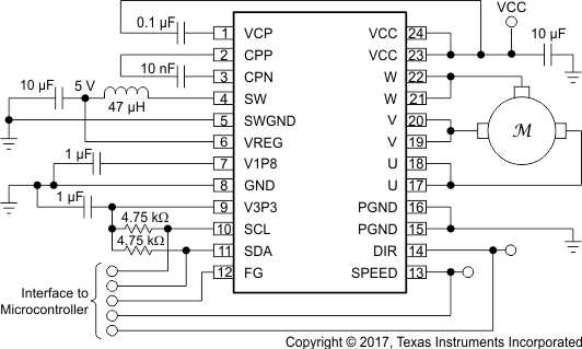
アプリケーションの回路図

4 改訂履歴
| 日付 | 改訂内容 | 注 |
|---|---|---|
| 2017年6月 | * | 初版 |