JAJSQ73C june 2014 – may 2023 TPS65263
PRODUCTION DATA
- 1
- 1 特長
- 2 アプリケーション
- 3 概要
- 4 Revision History
- 5 Device Comparison Table
- 6 Pin Configuration and Functions
- 7 Specifications
-
8 Detailed Description
- 8.1 Overview
- 8.2 Functional Block Diagram
- 8.3
Feature Description
- 8.3.1 Adjusting the Output Voltage
- 8.3.2 Enable and Adjusting UVLO
- 8.3.3 Soft-Start Time
- 8.3.4 Power-Up Sequencing
- 8.3.5 V7V Low Dropout Regulator and Bootstrap
- 8.3.6 Out-of-Phase Operation
- 8.3.7 Output Overvoltage Protection (OVP)
- 8.3.8 Pulse Skipping Mode (PSM)
- 8.3.9 Slope Compensation
- 8.3.10 Overcurrent Protection
- 8.3.11 Power Good
- 8.3.12 Thermal Shutdown
- 8.4 Device Functional Modes
- 8.5
Register Maps
- 8.5.1 Register Description
- 8.5.2 VOUT1_SEL: Vout1 Voltage Selection Register (offset = 0x00H)
- 8.5.3 VOUT2_SEL: Vout2 Voltage Selection Register (offset = 0x01H)
- 8.5.4 VOUT3_SEL: Vout3 Voltage Selection Register (offset = 0x02H)
- 8.5.5 VOUT1_COM: Buck1 Command Register (offset = 0x03H)
- 8.5.6 VOUT2_COM: Buck2 Command Register (offset = 0x04H)
- 8.5.7 VOUT3_COM: Buck3 Command Register (offset = 0x05H)
- 8.5.8 SYS_STATUS: System Status Register (offset = 0x06H)
- 9 Application and Implementation
- 10Device and Documentation Support
- 11Mechanical, Packaging, and Orderable Information
3 概要
TPS65263 には、入力電圧範囲が 4.5V~18V と広く、5、9、12、15V の電力バスまたはバッテリから動作するほとんどの中間バス電圧を網羅したトリプル同期整流降圧型コンバータが組み込まれています。定周波数ピーク電流モードを備えたこのコンバータは、目的のアプリケーションに合わせてシステムを最適化するための選択肢を設計者に与えると同時に、アプリケーションが簡単になるよう設計されています。このデバイスは 600kHz で動作し、buck1 と buck2 / buck3 の位相差は 180 度です (buck2 と buck3 は同相動作)。
各バックの初期スタートアップ電圧は、外付けのフィードバック抵抗で設定できます。各バックの出力電圧は、0.68~1.95V の範囲で、I2C 制御の 7 ビット VID を使用して 10mV 刻みで動的に設定可能です。VID 電圧の遷移スルーレートは、I2C バスによる 3 ビットの制御によりプログラム可能なため、VID 電圧遷移時のオーバーシュートやアンダーシュートを最適化できます。
TPS65263 の各バックについて、出力電圧のイネーブルとディセーブル、軽負荷時のパルス・スキップ・モード (PSM) または強制連続電流モード (FCC) の設定、パワー・グッド・ステータス、過電流警告、ダイ温度警告の読み出しを、I2C で制御できます。
TPS65263 には過電圧、過電流、短絡、過熱保護が搭載されています。
パッケージ情報 (1)
| 部品番号 | パッケージ | 本体サイズ (公称) |
|---|---|---|
| TPS65263 | RHB (VQFN、32) | 5.00mm × 5.00mm |
(1) 利用可能なすべてのパッケージについては、このデータシートの末尾にある注文情報を参照してください。
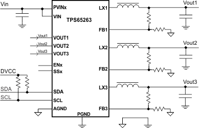
 代表的なアプリケーション
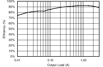
VIN = 12V、VOUT = 3.3V
効率と出力負荷との関係