SBAA438A June 2020 – March 2023 AMC1100 , AMC1200 , AMC1300B-Q1 , AMC1302 , AMC1311 , AMC1336 , AMC3301 , AMC3330 , ISO224
- Best in Class Radiated Emissions EMI Performance with Isolated Amplifiers
- Trademarks
- 1Introduction
- 2Current Generation of Texas Instruments Isolated Amplifiers Radiated Emissions Performance
- 3Previous Generations of Texas Instruments Isolated Amplifiers Radiated Emissions Performance
- 4Conclusion
- 5References
- 6Revision History
1 Introduction
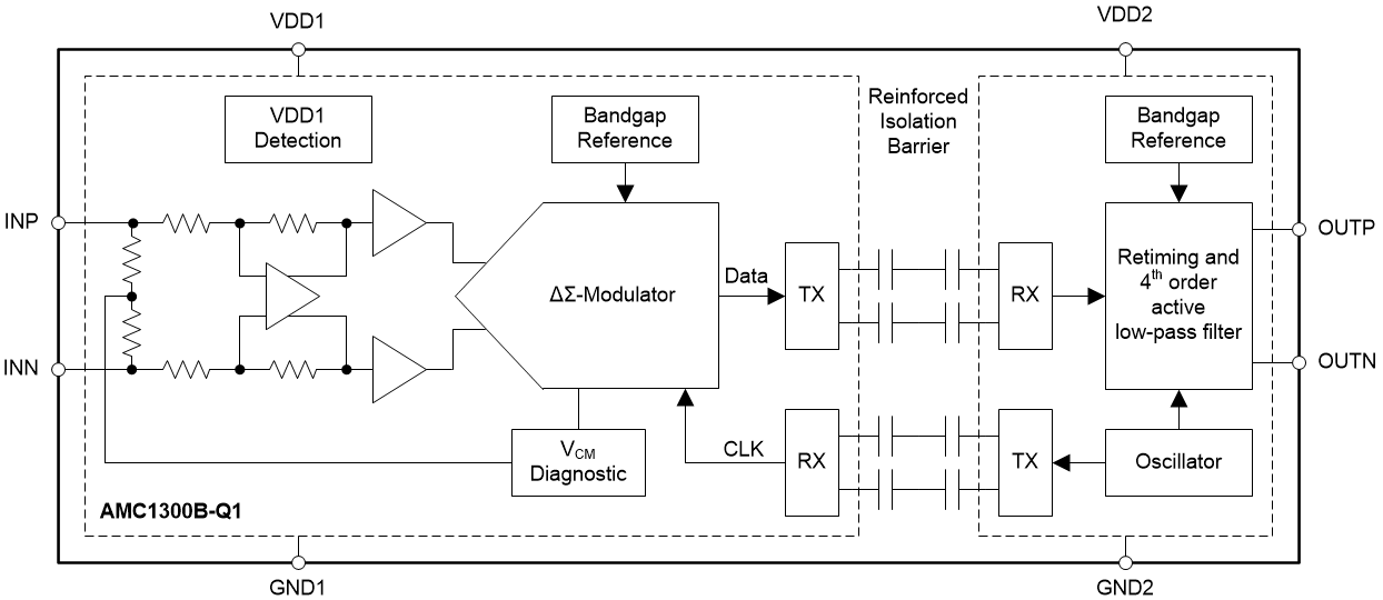
In isolated amplifiers with a capacitive isolation barrier, radiated emissions can be created when the capacitors that span the barrier are charged and discharged to transmit data in the form of either a 1 or a 0. The charges flow through the differential capacitors in opposite directions mostly canceling each other, however any difference in magnitude or time between these charge flows results in electro-magnetic energy injected between the isolated grounds GND1 and GND2. Because of the nature of the isolation barrier, the energy is unable to find a conductor to return to the source. With no path back to the source, the energy radiates from the device pins (and any traces or PCB planes they are connected to) in the form of radiated emissions. This radiation can extend to frequencies significantly above the amplifier signal bandwidth and data rates, since it is caused by timing mismatches in the pico-second range.
 Figure 1-1 Isolated Amplifier Block Diagram
Within the recent years, there have been significant improvements to the architecture of Texas Instruments isolated amplifiers to optimize radiated EMI performance. Beginning in 2018 with the ISO224, isolated amplifiers from Texas Instruments began to use on or off keying (OOK) signal modulation compared to previously used pulse coding. The OOK modulation enabled significantly improved Common-Mode Transient Immunity levels. Then in 2020, the AMC1300B-Q1 was the first isolated amplifier that significantly reduced the amount of energy crossing over the isolation barrier, which reduces the radiated emissions, providing sufficient margins to the standard specifications. These design changes, as well as a re-designed isolated signal path, are now present in the entire Texas Instruments isolated amplifier portfolio, with the exception of the AMC1100, AMC1200, and ISO224 devices. The optimized timing and amplitude in the signal chain yields a reduction of radiated emissions EMI at high frequencies to an even lower level.
The following sections show the radiated emissions EMI performance for the Texas Instruments' isolated amplifiers. The current generation of isolated amplifiers radiated emissions performance is shown by using the AMC1300B-Q1 as an example, while the ISO224 and AMC1200 are used to show data for the previous generation devices. The radiated emissions scans were all performed according to the standards set in place by CISPR 11. All tests were performed using the AMC1300EVM printed circuit board (PCB) with the inputs shorted to ground, transformer driver (U3) removed, and external 3.6 V batteries with short leads. Each scan shows the horizontal sweep results from the device under test (DUT) in blue as well as the ambient scan overlaid in red to show the noise floor of the chamber. Both CISPR 11 Class A and Class B limits are shown on the plots as well. The horizontal polarization was selected because the emissions levels detected by the test equipment’s antenna were higher than for the vertical polarization, due to alignment with the PCB.