SBAU336A March 2020 – March 2021 AMC3306M05 , AMC3306M25 , AMC3336 , AMC3336-Q1
2.1 Analog Inputs
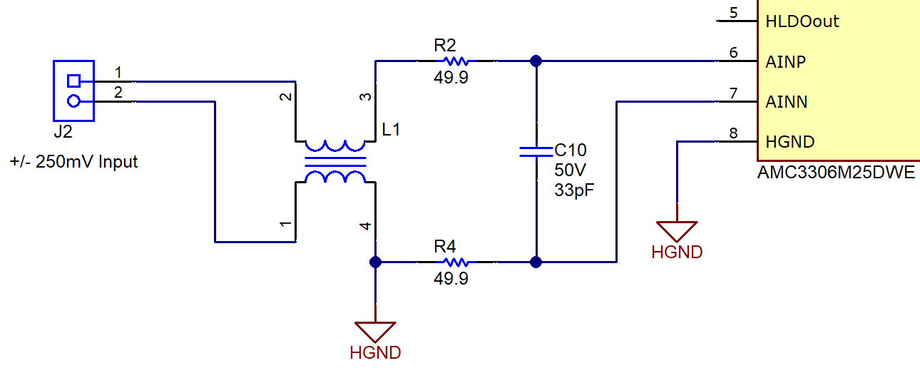
The analog inputs to the AMC33xxEVM printed-circuit board (PCB) consists of an RC filter circuit. By default, R7 and R11 on the analog input are populated as 49.9-Ω resistors. Capacitor C10, is populated with a 33-pF capacitor. Figure 2-1 shows an example input circuit for the AMC3306EVM. The analog input to the AMC3336EVM is identical to the AMC3306EVM, except the input range is ±1 V.
 Figure 2-1 AMC3306EVM Schematic: Analog Input Section