SBOA550 October 2022 OPA1671 , OPA2990 , SN74HCS04 , SN74HCS164 , SN74HCS30 , SN74LVC1G00 , SN74LVC1G123 , TLC04 , TLC14 , TS5A9411
- Abstract
- Trademarks
- 1 Introduction
- 2 The Davies Generator
- 3 Optimizing Standard Resistance Values for THD Performance
- 4 Simulation Examples
- 5 Compensating for Shift Register Output Resistance
- 6 Voltage-Mode Thevenin Equivalent
- 7 Harmonic Filtering
- 8 Tracking Harmonic Filter
- 9 Multiphase Output
- 10Conclusion
- 11Acknowledgment
- 12References
- A Analytical Solution for Resistance Network Values
- B Forbidden States of the Johnson Counter
7 Harmonic Filtering
Using the voltage mode of operation, adding one capacitor to the output creates a simple first-order low-pass filter, having a corner frequency of .
This smooths the steps of the waveform considerably and reduces THD by a factor of approximately 2 down to < 0.03%, see Figure 7-2, but a buffer is likely required to drive any subsequent circuit stage.
If a buffer is required, only an additional resistor (or two) and capacitor is needed to achieve a 2nd order filter. An active second-order Chebyshev harmonic filter having bandwidth of 1 kHz built using a high-quality op amp as shown in Figure 7-3, results in the response of Figure 7-4 while also providing a low impedance output for later stages. To minimize THD contribution from the op amp, the OPAx990 family is selected for superior linearity while the SPICE model is still realistic. Note that the bias shown for the op amp is symmetric about , where , and this common-mode voltage appears on the output as well.
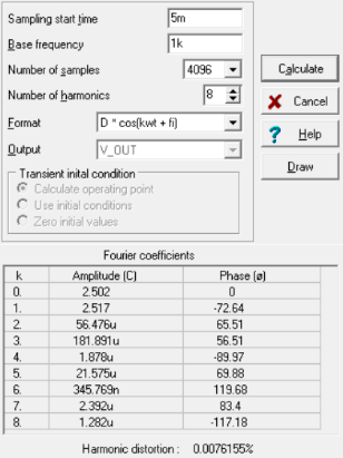
The transient simulation results and corresponding Fourier analysis indicate simulated THD < 0.01%.
 Figure 7-5 2nd and 3rd Harmonics are < –82 dB, Relative to the Fundamental
These results represent the most optimistic scenario where all resistor pairs are matched, there is no random tolerance variation from the chosen E96 series values, and using an aggressive Chebyshev 2nd order filter response. Real-world THD performance degrades as actual resistor tolerance (±1% for E96) manifests, but additional harmonic filtering or extending the register length are trade-offs to consider for improving performance if needed. The Chebyshev response has some pass-band ripple and additional phase shift, but other filter responses are available. The first 5 ms of simulation is ignored because it takes this time for the 2nd order filter to settle into steady-state operation.