SLAA843A August 2018 – March 2019 MSP430FR2512 , MSP430FR2512 , MSP430FR2522 , MSP430FR2522 , MSP430FR2532 , MSP430FR2532 , MSP430FR2533 , MSP430FR2533 , MSP430FR2632 , MSP430FR2632 , MSP430FR2633 , MSP430FR2633
5.2 Check Other Results
Section 3 introduces the result parameters (signal, noise, threshold, margin in, margin out, and SNR). The most important parameter to inspect are the Threshold and Margin In, which is the amount of additional noise that can be tolerated before a false detection occurs. This margin is needed to prevent increased external noise or an increased device noise from triggering a false detection. TI recommends having an Margin In value that is larger than the minimum recommended Margin In as showing in Table 4.
NOTE
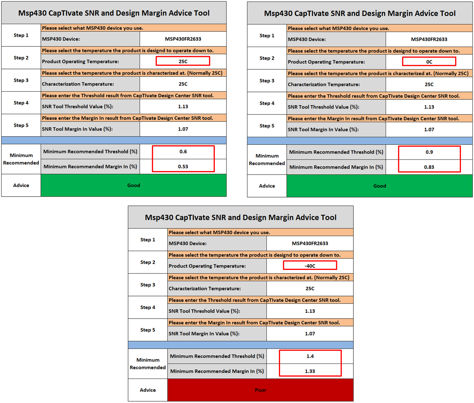
The CapTIvate Design Center SNR tool assumes the product is designed to operate down to 0°C and the characterization process is performed under normal room temperature at 25°C. To analyze the system under different operating or characterization temperature, you can either refer to Table 4 or use the CapTIvate SNR and Design Margin Advice Tool.
Example: The product uses the MSP430FR2633 device, and the designer wants to see the design margin analysis for operating temperatures of 25°C, 0°C, and -40°C with the characterization process performed at 25°C. The Threshold value (%) from the SNR tool is 1.13% and the Margin In value from the SNR tool is 1.07%. Figure 9 shows the CapTIvate SNR and Design Margin Advice Tool results for three different operating temperature. The tool outputs the Minimum Recommended Threshold, Minimum Recommended Margin In, and Advice based on the system conditions.
 Figure 9. CapTIvate SNR and Design Margin Advice Tool