SLAA843A August 2018 – March 2019 MSP430FR2512 , MSP430FR2512 , MSP430FR2522 , MSP430FR2522 , MSP430FR2532 , MSP430FR2532 , MSP430FR2533 , MSP430FR2533 , MSP430FR2632 , MSP430FR2632 , MSP430FR2633 , MSP430FR2633
3.3 Threshold (Sensitivity) (Th)
Sensitivity is a homonym in its use with capacitive sensing. Different individuals each tend to have their own definition of what sensitivity means to them. To bring clarity to this analysis, sensitivity is explicitly used in this document to describe the tuning of the detection threshold in units of percent change in capacitance. Defining sensitivity in the same units as signal and noise (percent change in capacitance) removes any dependence on the configuration of the analog front end and enables values to be compared easily.
As discussed in Section 1, touch and proximity detection reporting is based on a certain change in capacitance. The detection threshold that the user configures in the sensor tuning tab determines the magnitude of change that is required to trigger a touch or proximity detection during post processing of the raw data. As an example, if an application has a sensitivity level set to 5%, a detection is not triggered unless a change in capacitance is greater than 5%.
By defining sensitivity in this way (connecting it to the detection Threshold), it becomes a tuning property that expresses how sensitive the designer of the system has configured the capacitive touch implementation to be. The tuning process ultimately involves finding the best place for the detection threshold (and thus the sensitivity) that allows for good design margins relative to the signal and the noise.
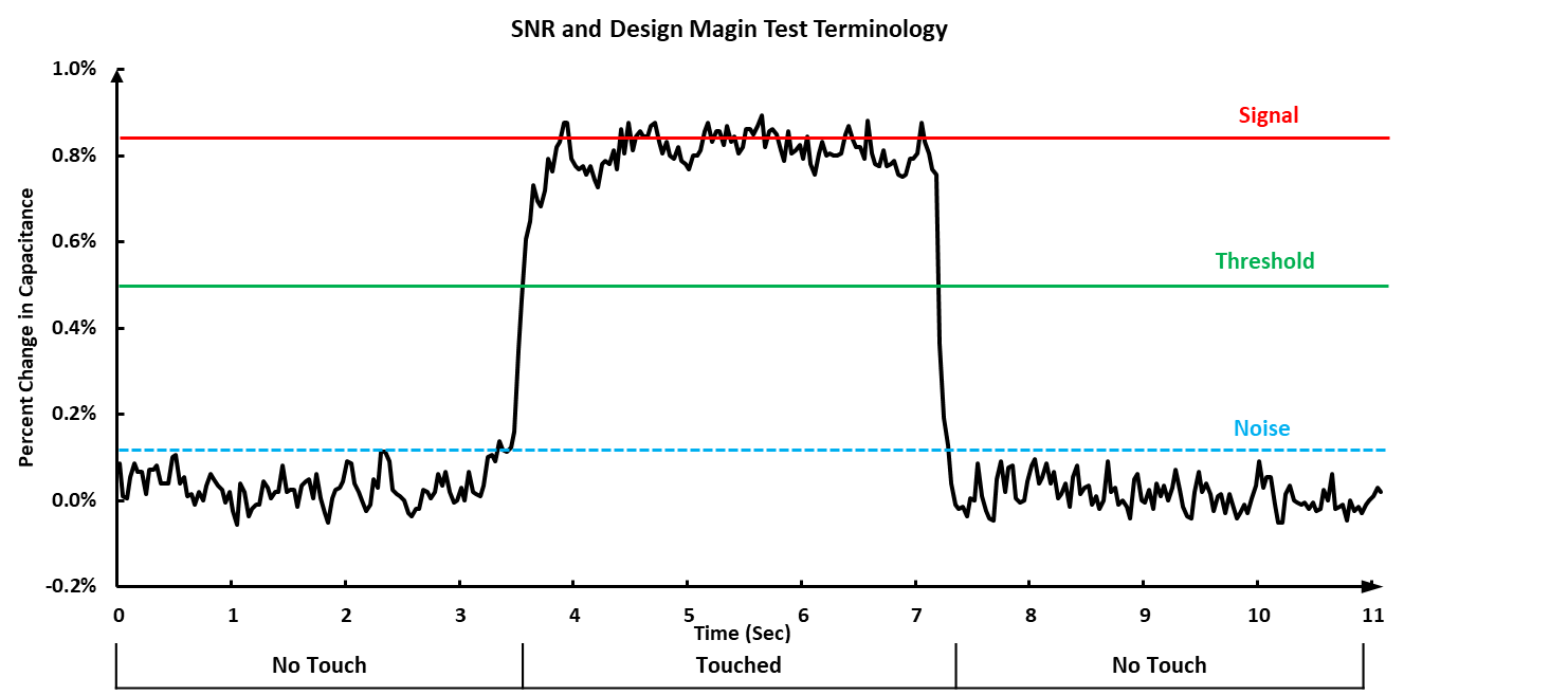
In this SNR analyze tool, the Threshold results are calculated based on the touch/proximity Threshold parameter that user selected in Tunning tab and it is in units of percent change in capacitance.
Figure 7 shows the self mode button measurement result in terms of percent change in capacitance for both touched and untouched conditions. The threshold configured by the user is defined as the percent change in capacitance (see the green "Threshold" line in the figure).
 Figure 7. Threshold Terminology
 NOTE
As the touch/proximity threshold is decreased (a lower percentage change in capacitance) the sensitivity of the application to touch or proximity is increased. A proximity application is considered high sensitivity, because it is attempting to detect a very small signal (a very small change in capacitance) using a very low detection Threshold (Th). As the sensitivity of an application goes up, the achievable SNR and design margins generally go down.