SLAU813A September   2019  – October 2020 TPA6304-Q1


  1.   Trademarks
  2. 1Required Equipment and Accessories:
  3. 2Hardware Overview
    1. 2.1 TPA6304Q1 Evaluation Module Description
    2. 2.2 TPA6304-Q1 Evaluation Module Functions
  4. 3Software Overview
    1. 3.1 PurePath™ Console 3 (PPC3) Access and Description
    2. 3.2 PurePath™ Console 3 – TPA6304Q1EVM Home Window
    3. 3.3 PurePath™ Console 3 – TPA6304Q1EVM Register Map Window
    4. 3.4 PurePath™ Console 3 – TPA6304Q1EVM Monitor & Control Window
  5. 4TPA6304-Q1 Start Up
    1. 4.1 TPA6304Q1EVM Setup
    2. 4.2 TPA6304-Q1 Settings on Device Monitor & Control Window
      1. 4.2.1 Device State Control Section
      2. 4.2.2 Channel Control Section
      3. 4.2.3 Miscellaneous Control Section
      4. 4.2.4 Fault / Warning Signal Configuration Section
      5. 4.2.5 Faults / Warnings Section
      6. 4.2.6 AC Load Diagnostics Section
      7. 4.2.7 DC Load Diagnostics Section
      8. 4.2.8 Spread Spectrum Control Section
    3. 4.3 TPA6304-Q1 Settings on Register Map Window
    4. 4.4 I2C Monitor Window
  6. 5Board Layout, Schematic and Bill of Materials
    1. 5.1 Board Layout
    2. 5.2 Schematic
    3. 5.3 Bill of Materials
  7.   Revision History

TPA6304Q1 Evaluation Module Description

The TPA6304Q1EVM is a stand-alone EVM. USB adapter is provided for a more thorough evaluation of the device. Figure 2-1 shows the EVM board.
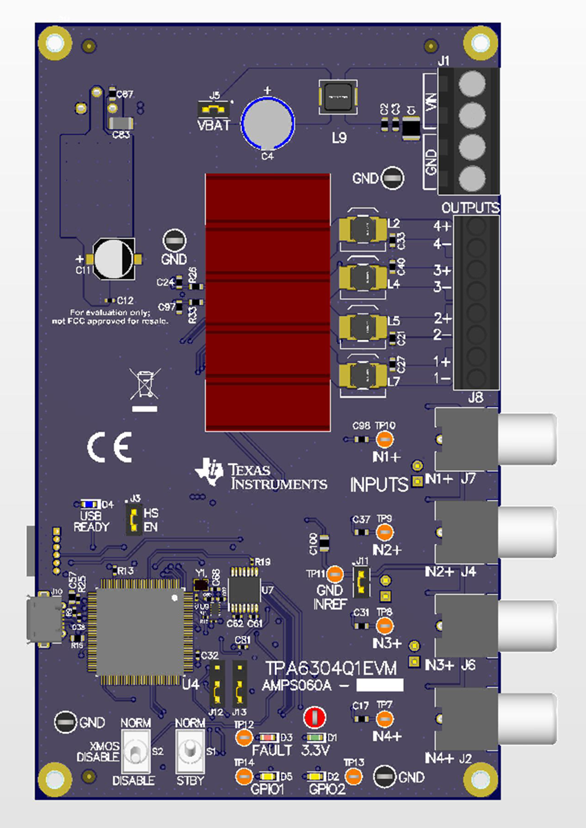
GUID-20200915-CA0I-1R9T-FB1Z-HWBL0154PBKS-low.pngFigure 2-1 TPA6304Q1EVM

Figure 2-2 shows the TPA6304Q1EVM signal flow:
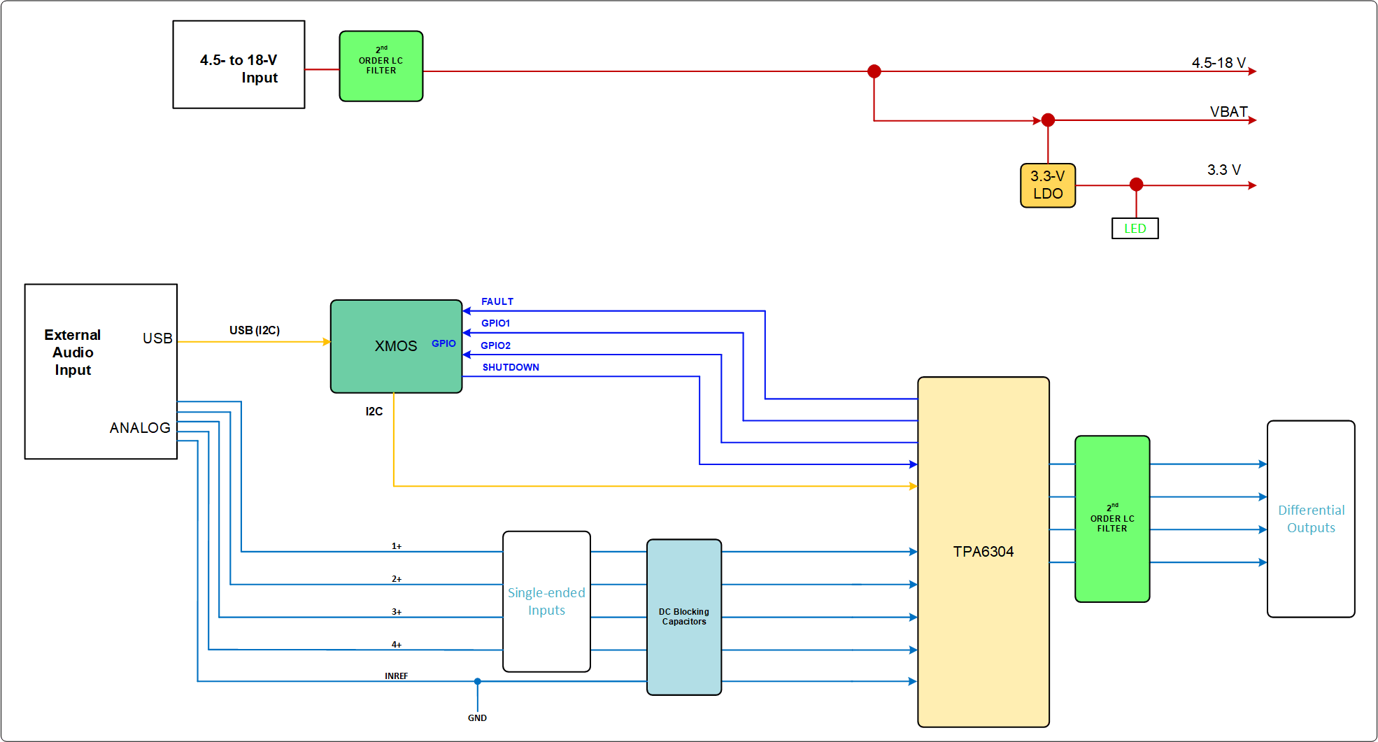
GUID-347338B7-D81D-4882-91E6-55CEE1E1C795-low.gifFigure 2-2 EVM Block Diagram