SLVAE51A November 2018 – October 2020 LM7310 , TPS2100 , TPS2101 , TPS2102 , TPS2103 , TPS2104 , TPS2105 , TPS2110 , TPS2111 , TPS2111A , TPS2112 , TPS2112A , TPS2113 , TPS2113A , TPS2114 , TPS2114A , TPS2115 , TPS2115A , TPS2120 , TPS2121 , TPS25947
2.1 Manual
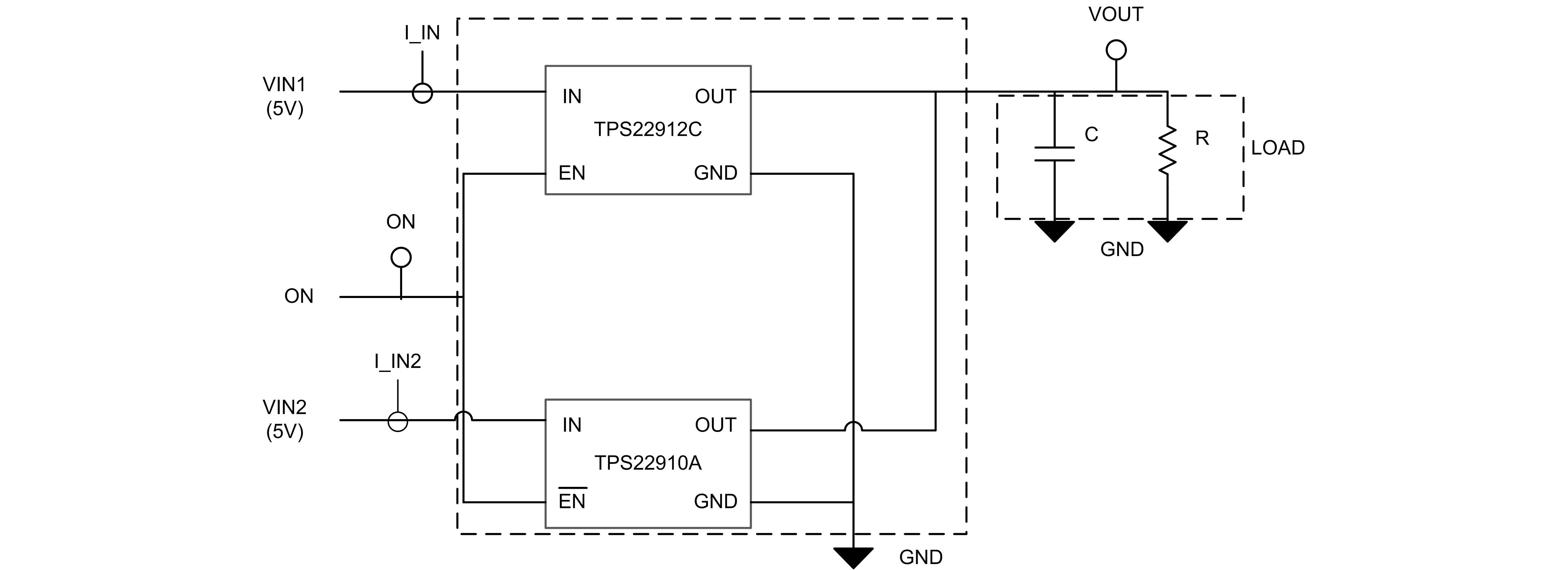
A manual power MUX is one in which each path is individually controlled by an external signal (logic or microcontroller). The example of two load switches used in Figure 2-1 is a manual power MUX. There could be one or two EN pins which need to be controlled. This method is generally used when there is already a microcontroller present in the system which can decide under what conditions to enable each input.
 Figure 2-1 Manual Power MUX using TPS22910 and TPS22912 Load Switches