SLVAE51A November 2018 – October 2020 LM7310 , TPS2100 , TPS2101 , TPS2102 , TPS2103 , TPS2104 , TPS2105 , TPS2110 , TPS2111 , TPS2111A , TPS2112 , TPS2112A , TPS2113 , TPS2113A , TPS2114 , TPS2114A , TPS2115 , TPS2115A , TPS2120 , TPS2121 , TPS25947
4.3 Output Voltage Drop
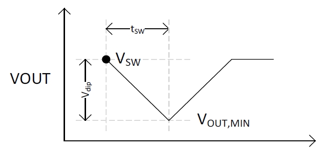
With a break-before-make power mux, there will be a period of time (tSW, switchover time) where the input supply is not providing power to the output. This will cause the output voltage to decay based on the following equations:
 Figure 4-1 Voltage Dip on Output During Switchover Time
Equation 1.
Equation 2.
Therefore a faster switchover time, tSW will result in a smaller voltage dip on the output, VDIP.