SLVAF59 April 2021 TPS2372 , TPS2373 , TPS23730 , TPS23731 , TPS23734 , TPS2375 , TPS2375-1 , TPS23750 , TPS23751 , TPS23752 , TPS23753A , TPS23754 , TPS23754-1 , TPS23755 , TPS23756 , TPS23757 , TPS23758 , TPS2376 , TPS2376-H , TPS2377 , TPS2377-1 , TPS23770 , TPS2378 , TPS2379
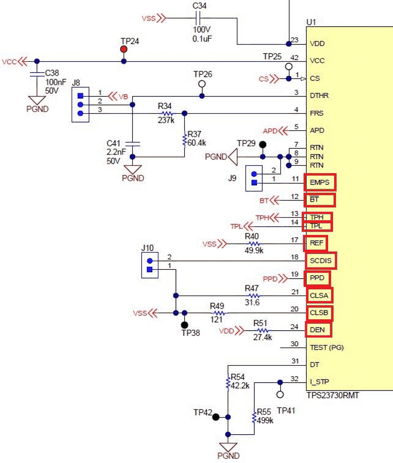
2.2 PoE Pin Settings
These pins are simple resistor and capacitor settings that tell about the PoE settings
- Check DEN: the resistor should be 24.9K if a diode bridge. If a hybrid or integrated rectifier, then a higher resistance is needed to account for the MOSFET having lower resistance than a diode. Use something between 25.5K and 27K as needed.
- Check the class resistors and ensure they are connected to VSS and are the correct class resistors for the power needed.
- If there is SCDIS ensure it is set properly as the MCU needs.
- REF should be a resistor to VSS as defined in the data sheet – use an EVM if the value cannot be found.
- If there is EMPS ensure it is set to what is needed: turn on Auto MPS or not.
- PPD enables wide-Vin applications for passive PoE.
 Figure 2-11 PoE IC Settings
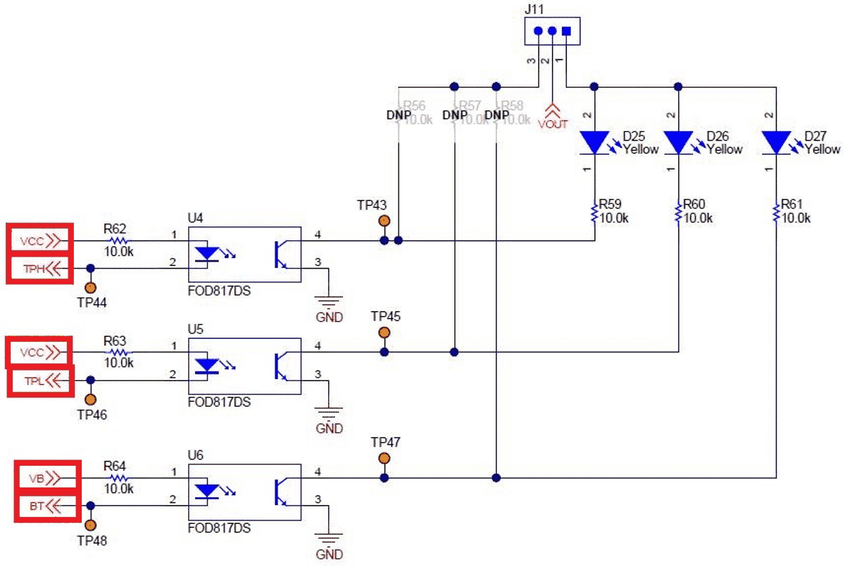
TPH, TPL, BT, T2P, and APO are all signals intended for an MCU. They should be connected to an optocoupler with pull ups to either VCC or VB as appropriate. VDD can also be used.
 Figure 2-12 TPH, TPL, and BT
Outputs