SLVUC46D March   2021  – November 2023


  1.   1
  2.   Abstract
  3.   Trademarks
  4. 1Introduction
    1. 1.1 Overview
      1. 1.1.1 Purpose and Scope
  5. 2Evaluation Hardware Overview
    1. 2.1 Connections Overview
    2. 2.2 Connection Details
      1. 2.2.1 Common Connectors and Headers Across all EVM Variants
      2. 2.2.2 MCU Reset and User Button
      3. 2.2.3 Communication Interfaces
      4. 2.2.4 Supply Input
      5. 2.2.5 Current Limit Header (RIPROPI)
      6. 2.2.6 Device Signal and Control Header
      7. 2.2.7 Device Signal Test Points
    3. 2.3 LED Indicators
    4. 2.4 Headers and Connectors (Hardware Device Variant)
    5. 2.5 Headers and Connectors (SPI variant)
  6. 3EVM GUI Control Application
    1. 3.1 MSP430 FET Drivers
    2. 3.2 Cloud-based GUI
    3. 3.3 Local Installation
  7. 4EVM GUI Operation
    1. 4.1 Hardware Setup
    2. 4.2 Launching the DRV824x_DRV814x-Q1EVM GUI Application
    3. 4.3 Using the DRV824x_DRV814x-Q1EVM GUI Application
      1. 4.3.1 Register Map Page (SPI Device Variant)
      2. 4.3.2 Driver Control Page (SPI Device Variant)
      3. 4.3.3 Driver Control Page (HW Device Variant)
      4. 4.3.4 Updating Firmware
  8. 5Revision History

Common Connectors and Headers Across all EVM Variants

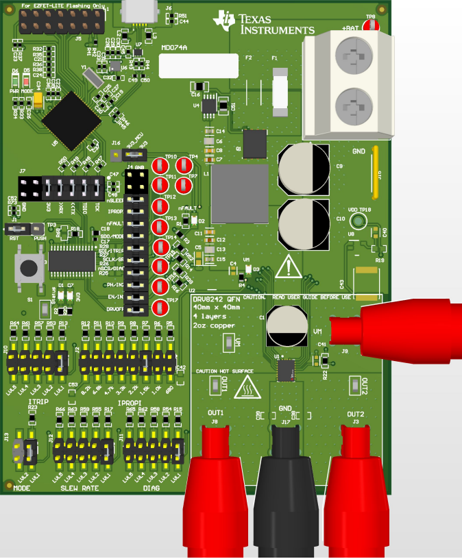
Figure 2-1 shows a larger view of the DRV824x-Q1EVM. Because the DRV814x-Q1EVM shares much of the same design, only the DRV824x-Q1EVM is referenced.

The micro-USB connection at the top of the EVM is used for GUI communications, and MCU firmware updates. Main supply input A supply voltage ranging from +4.5 VDC to +36 VDC from a battery or a DC voltage source is connected to the large screw thermal block (fused and reverse polarity protection).

Connect the bi-directional brushed-DC motors to the OUT1 and OUT2 banana jacks. Ground and VM supply connections are provided as a convenience for high-side or low-side switched loads (for example, unidirectional brushed DC motor or solenoid).
Note: VM has a small voltage drop with respect to the main supply due to the N-channel MOSFET in the reverse protection circuit.
GUID-20230926-SS0I-DWGV-NXWL-5S2QFM1LTRGW-low.png Figure 2-1 DRV824x-Q1EVM