SLWU095 april 2023
5 Downloading Firmware
The TSW14J59EVM has an
Xilinx® Kintex® UltraScale® XCKU5P device that
requires firmware to be downloaded every time power is cycled to operate if the
on-board EEPROM's are not programmed. The firmware files needed are special .bin or
.bit formatted files that are provided with the software package. The files used by
the GUI reside in the directory called
C:\Program
Files\Texas Instruments\High Speed Data Converter Pro\14J59 Details\Firmware. Follow
the steps below:
- After connecting to the GUI, a new window opens.
- Click on the drop down arrow which opens another window. Select either ADC, DAC or AFE, based on which data converter EVM is being tested.
- After making this selection, click on the drop down arrow in the upper left of
the GUI to select the device name and JMODE as shown in Figure 5-1.
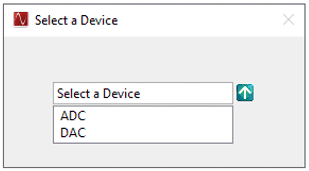 Figure 5-1 Select ADC or DAC
Firmware to be Loaded
 - Click on the drop down arrow in
the upper left of the GUI next to Select ADC and device mode.
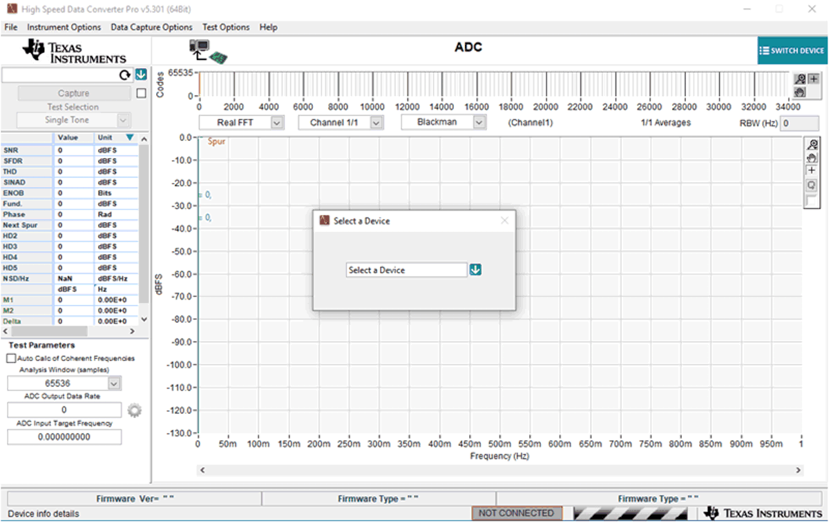 Figure 5-2 High-Speed Data
Converter Pro GUI Top Level
 - Click
on the two drop down arrows in the upper left of the GUI to select the device
name and JMODE, for example, ADC12DJxx00 and JMODE30.
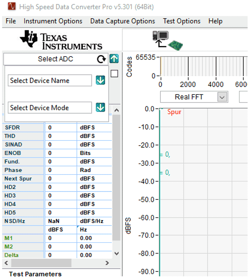 Figure 5-3 Select Device Under Test and Operating Mode
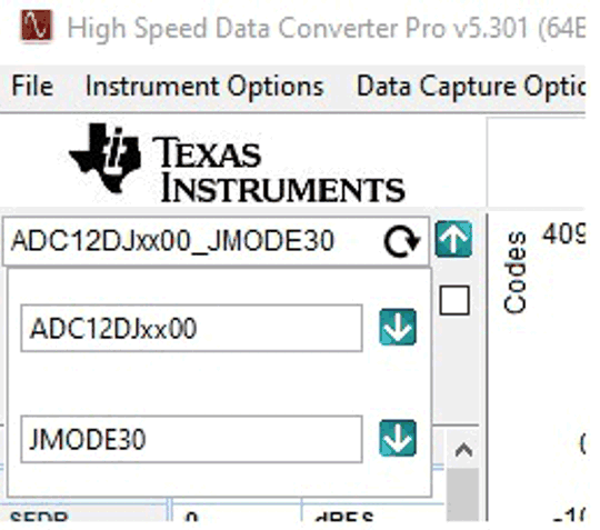 Figure 5-4 Example When Connected
to an ADC12DJ3200EVM Using JMODE30
 - The GUI prompts the user to update the firmware for the ADC. Click Yes. The GUI displays the message Downloading Firmware, Please Wait. The software now loads the firmware from the PC to the FPGA, a process that takes about 6 seconds. Once completed, the GUI reports an Interface Type in the lower right corner and red LEDs DS16 and DS17 turns on.
For information regarding the use of the TSW14J59EVM with a TI ADC, DAC or AFE JESD204C_B serial interface EVM, consult the High-Speed Data Converter Pro GUI User's Guide and the individual EVM User’s Guide, available on www.ti.com.
If the message appears as shown in c, then verify that all jumpers are in the default position and the power and USB status LEDs are illuminated. If the 12-V power status LED is off, then there can be a problem with the external power supply. Make sure this supply can source at least 3 A of current. If the available current is too low, then this can prevent the firmware from downloading. Unplug and re-install the USB connectors and try to connect to the board. If this fails, then cycle the power switch to re-initialize the power-up sequencer to try to correct this problem.
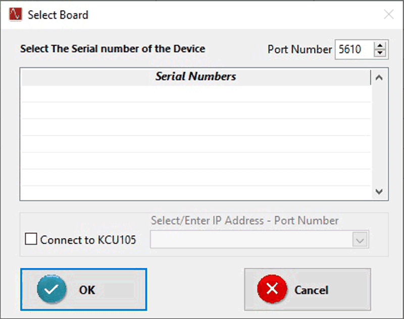 Figure 5-5 GUI Does Not Connect to
EVM