SLWU095 april 2023
4.2 USB Interface and Drivers
- Connect a USB 3.0 cable between J9 of the TSW14J59EVM and a host PC.
- Connect the provided power cable between J38 of the EVM and a +12 VDC source rated for at least 3 A.
- Set SW1 to ON. LEDs D21 (+12 V present), D22 (power monitor supply), and several power status LEDs are turned on.
- Click on the High-Speed Data Converter Pro icon that was created on the desktop panel, or go to C:\Program Files\Texas Instruments\High Speed Data Converter Pro and double click on the executable called High Speed Data Converter Pro.exe to start the GUI.
- The GUI first attempts to connect to the EVM USB interface. If the GUI identifies a
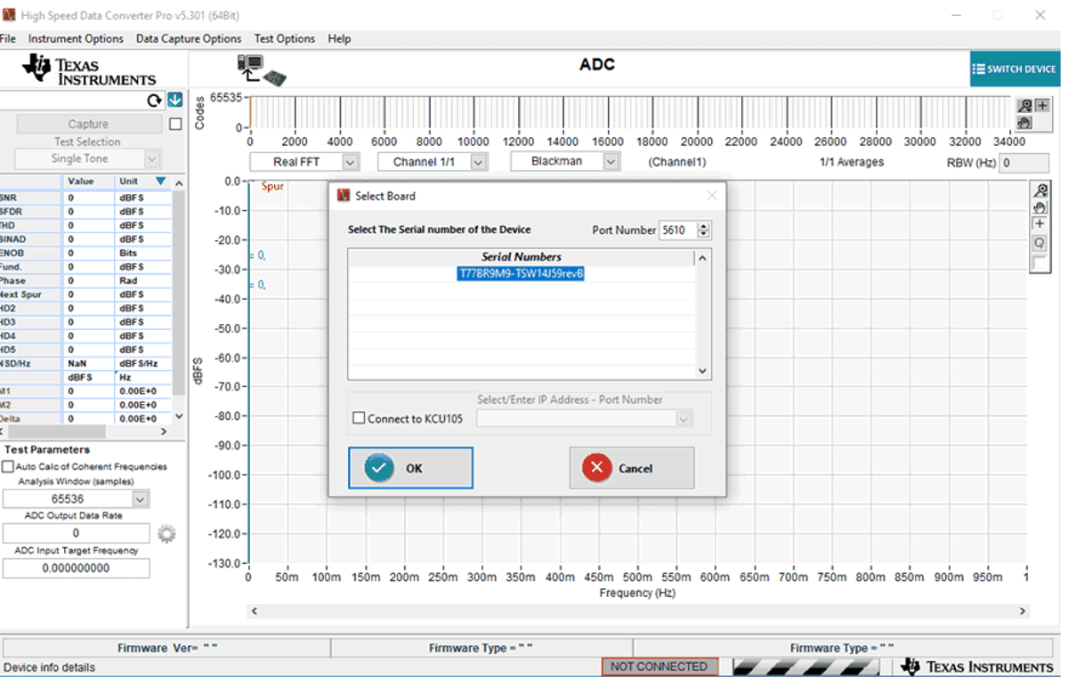
valid board serial number, then a pop-up opens displaying this value, as Figure 4-1 shows. The user can connect several TSW14J59 EVMs to one host PC, but the GUI can only
connect to one at a time. When multiple boards are connected to the PC, the pop-up
displays all of the serial numbers found. The user then selects which board to associate
the GUI with.
 Figure 4-1 TSW14J59EVM Serial Number
 - Click the OK button to connect the GUI to the board. The top-level GUI opens and appears.
- If the message No Board Connected opens, then double check the USB cable connections and that power switch SW1 is in the on position. Remove the USB3.0 cable from the board then re-install. Click on the Instrument Option tab at the top left of the GUI and selecting Connect to the Board. If this still does not correct this issue, then check the status of the host USB port.
- When the software is installed and the USB cables are connected to the TSW14J59EVM and
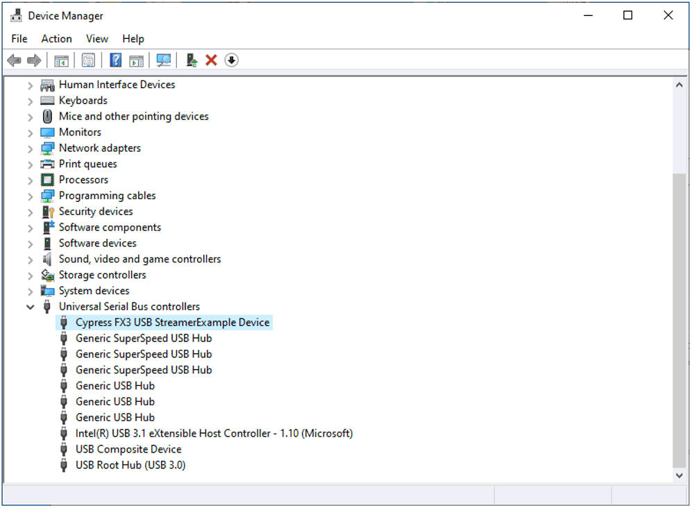
the PC, the TSW14J59 USB 3.0 converter is located in the Hardware Device Manager under the
universal serial bus controllers as shown in Figure 4-2, labeled as Cypress FX3 USB StreamerExampleDevice. When the USB 3.0 cable is removed,
this driver is no longer visible in the device manager. If the drivers are present in the
device manager window and the software still does not connect, then remove the USB cable
from the board then reconnect the cable. Attempt to connect to the board using the GUI. If
the problem still exists, then cycle power to the board and repeat the prior steps.
 Figure 4-2 Hardware Device Manager