SNAU291 October   2023


  1.   1
  2.   Description
  3.   Features
  4.   Applications
  5.   5
  6. 1Evaluation Module Overview
    1. 1.1 Introduction
    2. 1.2 Kit Contents
    3. 1.3 Specification
    4. 1.4 Device Information
  7. 2Hardware
    1. 2.1 EVM Quick Start
      1. 2.1.1 Hardware Setup
      2. 2.1.2 EVM Measurements
    2. 2.2 Device Operation Modes
    3. 2.3 EVM Configuration
      1. 2.3.1 Power Supply
      2. 2.3.2 Logic Input and Outputs
      3. 2.3.3 Clock Input
      4. 2.3.4 Clock Outputs
      5. 2.3.5 Status Outputs, LEDs and Test Points
  8. 3Software
    1. 3.1 Software Installation
      1. 3.1.1 Software Setup
      2. 3.1.2 Program and Setup
    2. 3.2 TICS Pro LMKDB1108 Software
      1. 3.2.1 Input
        1. 3.2.1.1 Input Interface Type
        2. 3.2.1.2 Input Termination
        3. 3.2.1.3 Auto Output Disable (AOD)
        4. 3.2.1.4 LOS Event
        5. 3.2.1.5 LOS Readback
      2. 3.2.2 Device Info
        1. 3.2.2.1 EVM Setup
        2. 3.2.2.2 SMBus
      3. 3.2.3 Output
        1. 3.2.3.1 SMBus
        2. 3.2.3.2 OE Pin Control
        3. 3.2.3.3 Side Band Interface (SBI)
  9. 4Implementation Results
    1. 4.1 Typical Phase Noise Characteristic
  10. 5Hardware Design Files
    1. 5.1 Schematics
    2. 5.2 PCB Layouts
    3. 5.3 Bill of Materials (BOM)
  11. 6Compliance Information
    1. 6.1 Compliance and Certifications
  12. 7References

Software Setup

  1. If not already installed, then install TICS Pro software from TI website: TICS Pro Software GUI.
  2. Start TICS Pro software.
  3. Select the LMKDB1108 profile from Select Device Clock Distribution with DividerLMKDB1108.
  4. Confirm communication with the board as follows:
    1. Click USB Communication from the menu bar.
    2. Click Interface to launch the Communication Setup pop-up window.
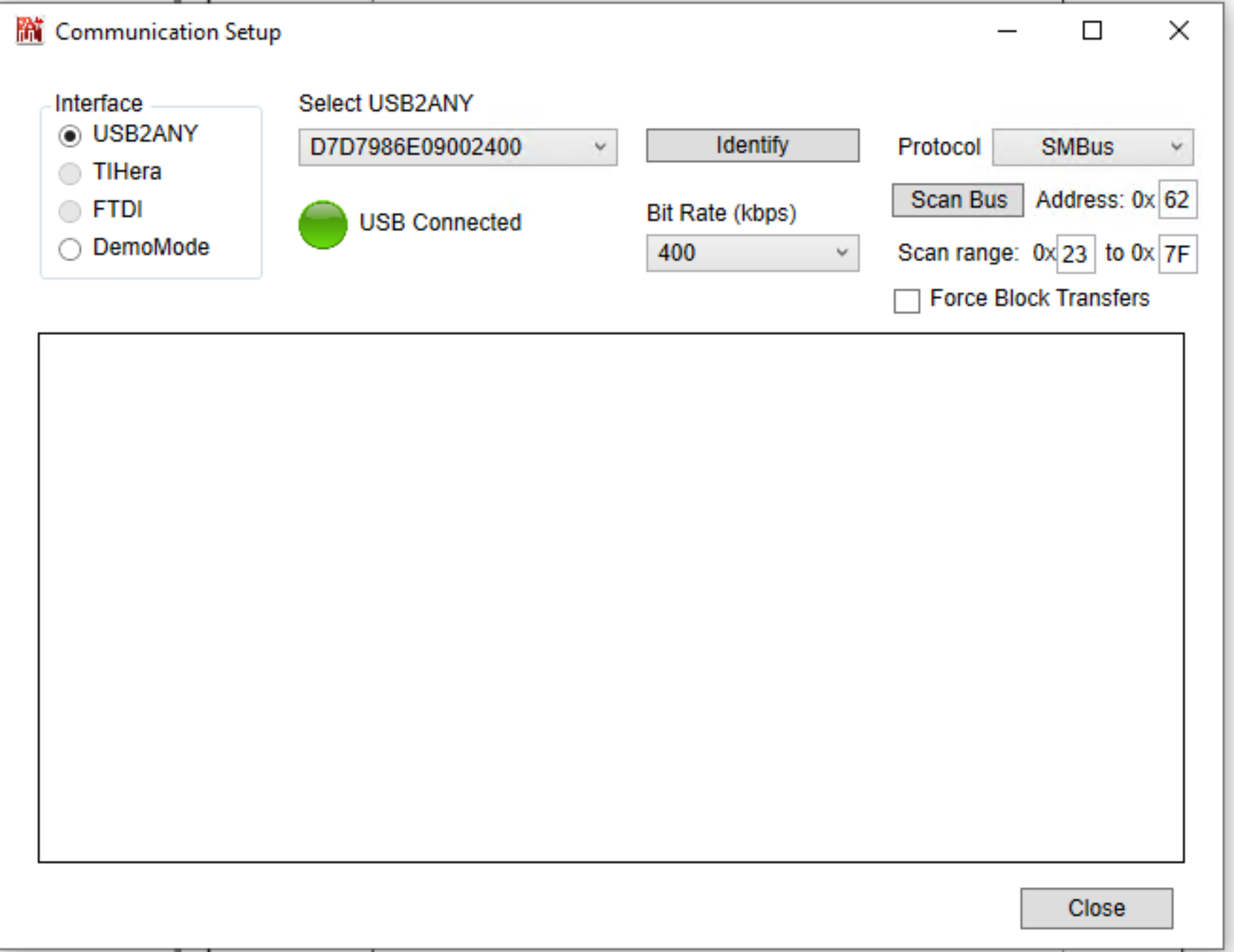
    3. Confirm following field the Communication Setup pop-up window:
      1. Make sure USB2ANY is selected as the interface.
      2. In case of multiple USB2ANY, select desired interface. If a USB2ANY is currently in use in another TICS Pro, then the user must release that interface by changing the interface setting to DemoMode.
      3. Click Identify to blink LED shown in Figure 4-1. After clicking the Identify button, the LED flashes quickly at about 0.5 second on, 0.5 second off for about 5 seconds. This confirms the connection to the board. However, be aware that USB2ANY devices connected to the PC, but not attached to a TICS Pro instance, can blink at a slow rate of 1 second on, 1 second off continuously.
    4. Confirm all the fields match the ones shown in Figure 4-2.
      GUID-20231012-SS0I-PNBD-X9T2-CZKDCNQCL5HC-low.svg Figure 3-1 USB LED
      GUID-20231009-SS0I-10CF-T9V0-H2FVFZ2WNXGV-low.png Figure 3-2 Communication Setup