SNLA437 December 2023 DP83822H , DP83822HF , DP83822I , DP83822IF , DP83825I , DP83826E , DP83826I
- 1
- Abstract
- Trademarks
- 1DP83822 Application Overview
-
2Troubleshooting the PHY Application
- 2.1 Schematic and Layout Checklist
- 2.2 Verify Successful Power-up of PHY
- 2.3 Read and Check Register Values
- 2.4 Peripheral Pin Checks
- 2.5 Verifying Strap Configurations During Initialization
- 2.6 Debugging Link Quality
- 2.7 Built-In Self Test With Various Loopback Modes
- 2.8 Debug the Fiber Connection
- 2.9 Debug the MAC Interface
- 2.10 Debug the Start of Frame Detect
- 2.11 Tools and References
- 3References
2.8 Debug the Fiber Connection
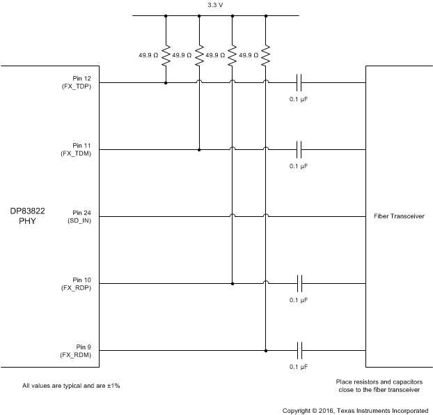
Fiber Network Circuit shows the recommended circuit for a 100-Mbps fiber network. Variations with PCB and component characteristics require that the application be tested to verify that the circuit meets the requirements of the intended application.
All resistors and capacitors should be placed as close to the fiber transceiver as possible.
 Figure 2-11 Fiber
Network Circuit
Figure 2-11 Fiber
Network CircuitThe DP83822 provides IEEE 802.3 compliant 100BASE-FX operation. Hardware bootstrap or register configuration can be used to enable 100BASE-FX operation.
The DP83822IF and DP83822HF are the fiber capable variants of the DP83822. Bit 2 in Register 0x0001 indicates link status for both Copper and Fiber modes of operation. In copper mode, this register behaves as expected: Bit 12 will toggle between '1' and '0' according to the Link Status. However in Fiber, this bit will not toggle when the link status changes. In order to check the link status accurately, a Soft-Reset must be performed (Set Register 0x001F = 4000) before reading Register 0x0001.
The DP83822 also has the added feature of a signal detection pin for direct connection to an industry standard fiber transceiver. When enabling 100BASE-FX operation using the FX_EN bootstrap, AMDIX_EN bootstrap turns into SD_EN bootstrap. If 100BASE-FX operation is enabled by setting FX_EN to either bootstrap mode 2 or 3, SD_EN will enable signal detection pin, LED_1, when SD_EN is set to either bootstrap mode 3 or 4. Please see Verify Strap Configurations During Initialization for mode information regarding hardware bootstraps.
| Pin Name | Pin# | PU/PD | Mode | Description |
|---|---|---|---|---|
| COL | 29 | PU | 2 or 3 | FX_EN: Enables 100BASE-FX |
| RX_ER | 28 | PU | 3 or 4 | SD_EN: Enables 100BASE-FX Signal Detection on LED_1 when set to '1'. FX_EN strap must be enabled for SD_EN strap to be functional. Signal Detection is Active HIGH, but polarity can be changed using the Fiber General Configuration Register (FIBER GENCFG, Register 0x0465). |
| Bit | Name | Type | Default | Function |
|---|---|---|---|---|
| 0 | 100Base-FX Signal Detect Polarity | R/W | 0 | 100Base-FX Signal Detect Polarity: 1 = Signal Detect is Active LOW 0 = Signal Detect is Active HIGH When set to Active HIGH, Link drop will occur if SD pin senses a LOW state (SD = '0'). When set to Active LOW, Link drop will occur if SD pin senses a HIGH state (SD = '1'). Note: To enable 100BaseFX Signal Detection on LED_1 (pin #24), strap SD_EN = '1' |