SNOA963B February 2020 – July 2021 LDC2112 , LDC2114 , LDC3114 , LDC3114-Q1
2 LDC211x and LDC3114 Gain Settings
Section 1 highlights that inductive touch button sensitivity can be affected by a few different factors. Some of these factors relate to the mechanical design and construction of the button enclosure and are sometimes complex to control or change in an existing design.
The LDC211x and LDC3114 devices address the need to control the sensitivity of inductive touch buttons through an easy-to-use register setting. Button sensitivity can be precisely tuned by adjusting the GAINn registers (0x0E, 0x10, 0x12, and 0x13) in these LDC devices.
The GAINn register field scales the normalized 12-bit DATAn output value. A higher GAINn value results in a higher DATAn value for a given amount of force applied to the target conductive surface. The 6-bit GAINn setting can be used to set the gain factor to values between 1 and 232. Each incremental GAINn value increases the gain factor by an average of 9% which provides enough granularity to precisely control the button sensitivity.
The GAINn setting does not affect the amount of deflection experienced by the button surface for a given amount of force nor does it affect the amount of inductance shift experienced by the inductive sensor.
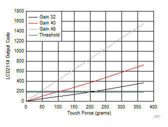
Figure 2-1 shows how the button threshold can be configured to different amount of button activation force by simply tuning the GAINn register settings:
 Figure 2-1 Gain and Button Threshold
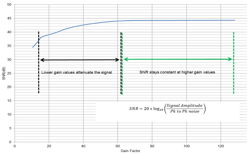
It is important to remember that the GAINn setting does not have a significant impact on the noise observed on the DATAn output. This is a result of the extremely low noise architecture of the LDC211x and LDC3114 devices. Figure 2-2 shows SNR for a given amount of force across a range of gain factors:
 Figure 2-2 SNR (dB) vs Gain Factor