SPRACT7 August 2020 TMS320F280021 , TMS320F280021-Q1 , TMS320F280023 , TMS320F280023-Q1 , TMS320F280023C , TMS320F280025 , TMS320F280025-Q1 , TMS320F280025C , TMS320F280025C-Q1 , TMS320F280040-Q1 , TMS320F280040C-Q1 , TMS320F280041 , TMS320F280041-Q1 , TMS320F280041C , TMS320F280041C-Q1 , TMS320F280045 , TMS320F280048-Q1 , TMS320F280048C-Q1 , TMS320F280049 , TMS320F280049-Q1 , TMS320F280049C , TMS320F280049C-Q1
3.1 Duty Cycle Compensation
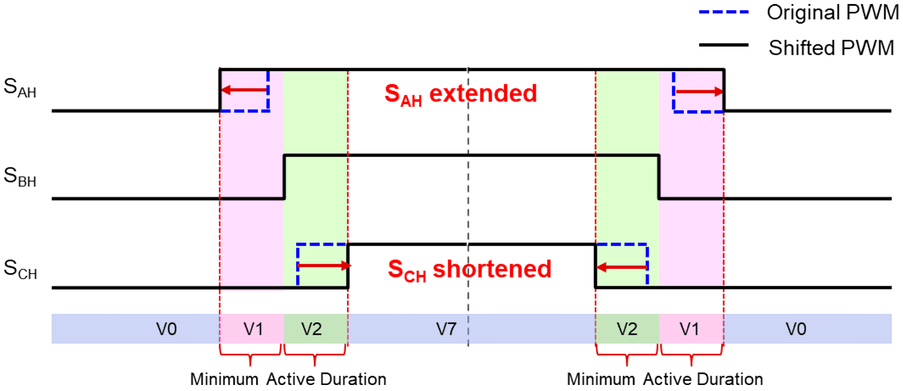
This method is relatively simple and can be used with same ePWM settings for symmetric SVPWM. After finding maximum and minimum duty cycle, the maximum duty cycle is extended up to minimum active duration if the V1 vector between maximum and middle duty cycle is less than the minimum active duration get in Equation 2. Also, the minimum duty cycle should be shortened up to minimum active duration if the V2 vector between middle and minimum duty cycle is less than the minimum active duration. The PWM channel with midrange duty cycle remains unchanged.
In this method, the distortion of the phase current is relatively large because average output voltage is not same with the original output voltage command.
 Figure 3-1 PWM Duty Cycle
Compensation
Figure 3-1 PWM Duty Cycle
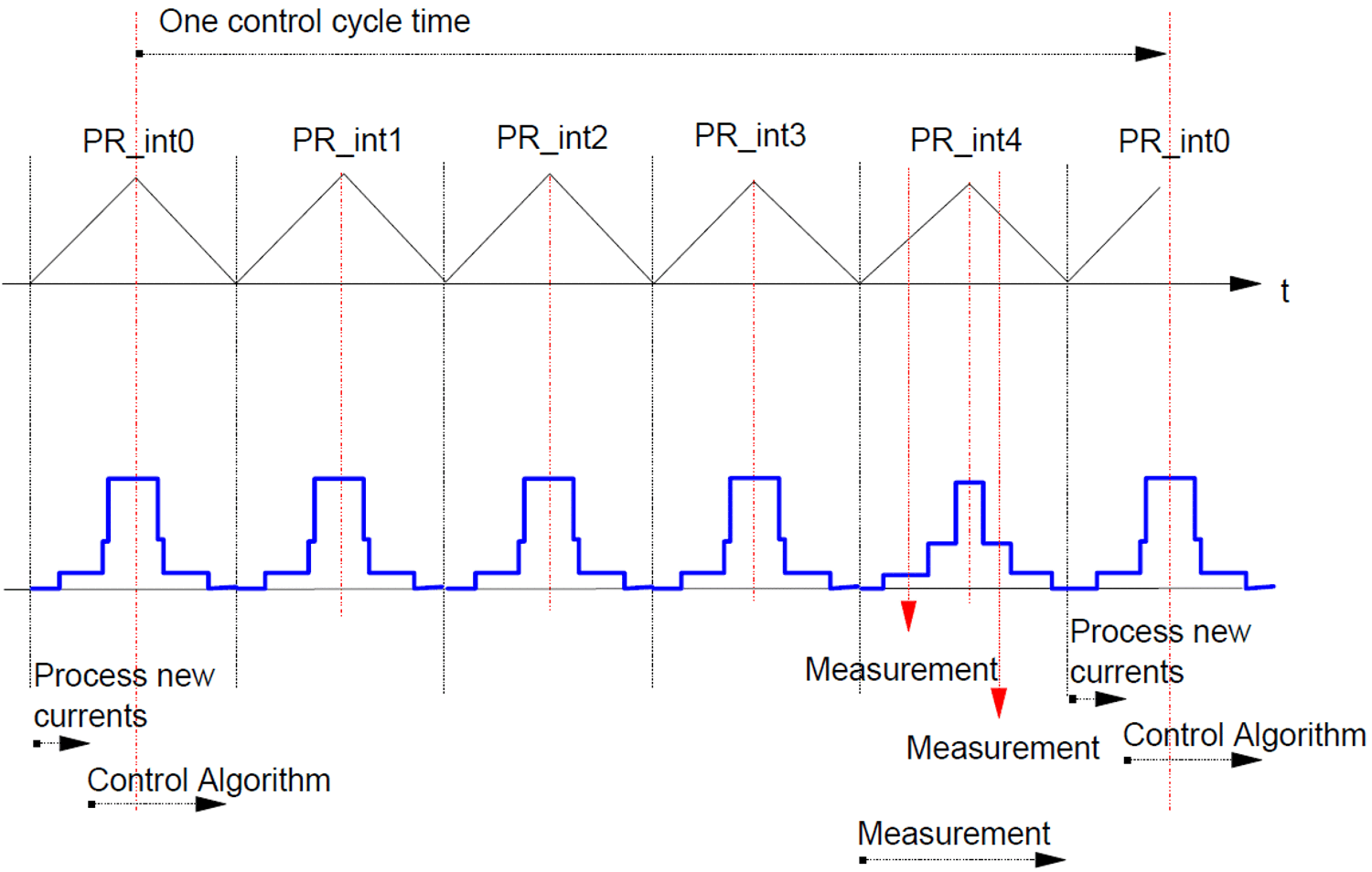
CompensationIf the phase currents should be sampled at every control cycle, V1 and V2 should always have sufficiently large active voltage duration. However, if the current control is performed once every multiple PWM periods, this duty cycle compensation method can be a good solution for single-shunt current measurement because phase current distortion happens just one time for multiple PWM periods. The Synchronization Diagram of the Control image in the Measurement Process section of Three phase current measurements using a single line resistor on the TMS320F240 (BPRA077) shows this example that the current control is performed once every five PWM periods. Then only two dc link current measurements are required to get the phase currents every five PWM periods.
This method is available to the applications that do not need high current bandwidth. On the contrary, for the high current bandwidth, another PWM compensation method explained next chapter will be good solution.
 Figure 3-2 Advanced Duty Cycle
Compensation