SPRACT7 August 2020 TMS320F280021 , TMS320F280021-Q1 , TMS320F280023 , TMS320F280023-Q1 , TMS320F280023C , TMS320F280025 , TMS320F280025-Q1 , TMS320F280025C , TMS320F280025C-Q1 , TMS320F280040-Q1 , TMS320F280040C-Q1 , TMS320F280041 , TMS320F280041-Q1 , TMS320F280041C , TMS320F280041C-Q1 , TMS320F280045 , TMS320F280048-Q1 , TMS320F280048C-Q1 , TMS320F280049 , TMS320F280049-Q1 , TMS320F280049C , TMS320F280049C-Q1
2.1 Basic Theory of FOC
The torque in the synchronous machine is vector cross product of the stator field or current vector and rotor magnetic field vector as following.

The K is constant and the amplitude of torque is proportion to the amplitude of rotor flux vector, the amplitude of stator current vector and sinθ which is angle between rotor flux and stator current vector. This expression shows that stator current vector and rotor magnetic field vector should be orthogonal to get maximum torque with given stator current. To keep the angle at 90 degrees, we have to know the rotor position. This can be achieved with a position sensor like encoder or resolver. Also, rotor position can be estimated by using sensorless technologies like InstaSPIN-FOC without these kinds of position sensors.
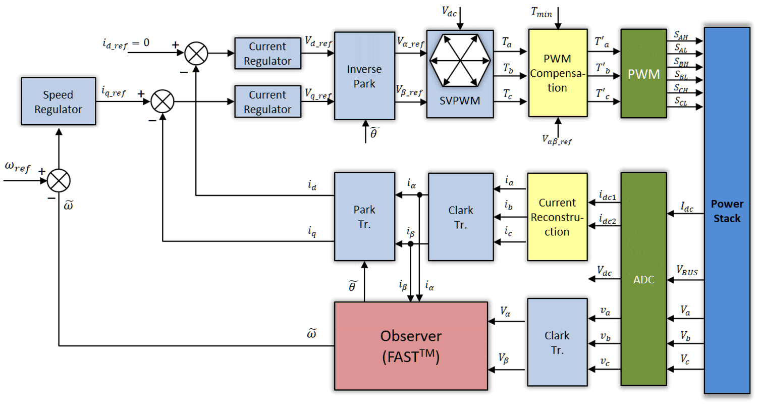
In brief, the goal of FOC is to control stator current vector based on rotor flux vector. For best performance, FOC algorithm aligns the stator current vector to 90° of the rotor flux vector, such that, orthogonal to the rotor flux vector. To do this, a three-phase stator current is measured by shunts or in-line magnetic based current sensors. A three sensors measurement can get the best performance in the most of applications. In particular area, a single sensor measurement can be used for a BOM cost saving and an easy pcb layout. If a single sensor is used for current measurement, a special algorithm is need for three phase current reconstruction. These current measurements feed into the Clarke transformation module. The outputs of this projection designated iα and iβ are the inputs of the Park transformation that gives the current in the d,q rotating reference frame. The id and iq components are compared to the references id_ref (the flux reference) and iq_ref (the torque reference). For controlling a non-saliency PMSM, id_ref will be set to zero except flux-weakening control mode. The torque command iq_ref could be the output of the speed regulator when using a speed controller. The outputs of the current regulators are Vd_ref and Vq_ref; they are applied to the inverse Park transformation. The outputs of this projection are Vα_ref and Vβ_ref, which are the components of the stator vector voltage in the (α,β) stationary orthogonal reference frame. These are the inputs of the Space Vector PWM (SVM). The outputs of this SVM block are the signals that drive the inverter. For single-shunt measurement, the switching pattern of SVPWM is modified to reconstruct the phase current in the unmeasurable area. Note that both Park and inverse Park transformations need the rotor flux position. So, knowledge of the rotor flux position is the core of the FOC.
 Figure 2-1 Block Diagram of Sensorless FOC
With Single Current Sensor at DC Link