SPRACT7 August 2020 TMS320F280021 , TMS320F280021-Q1 , TMS320F280023 , TMS320F280023-Q1 , TMS320F280023C , TMS320F280025 , TMS320F280025-Q1 , TMS320F280025C , TMS320F280025C-Q1 , TMS320F280040-Q1 , TMS320F280040C-Q1 , TMS320F280041 , TMS320F280041-Q1 , TMS320F280041C , TMS320F280041C-Q1 , TMS320F280045 , TMS320F280048-Q1 , TMS320F280048C-Q1 , TMS320F280049 , TMS320F280049-Q1 , TMS320F280049C , TMS320F280049C-Q1
3.3 Current Reconstruction
The sampled dc link currents based on the timing diagram on Figure 2-12 can be reconstructed to three-phase currents by using the information in Table 3-1. The sector number calculated in Equation 4 is used here. The first sampled dc link current (Idc_sample1) is measured at the first active vector duration during EPWMx down counter. And, the second dc link current (Idc_sample2) is measured at the second active vector duration during the same EPWMx down counter. The last one that was not directly measured from shunt can be calculated by using the principle of Kirchhoff’s Current Law (KCL) that the sum of the currents into a single node equals zero.
| Sector | Phase Current (Ia, Ib, Ic) |
|---|---|
| 1 | Ic = -Idc_sample1, Ia = Idc_sample2, Ib = -(Ia + Ic) |
| 2 | Ic = -Idc_sample1, Ib = Idc_sample2, Ia = -(Ib + Ic) |
| 3 | Ia = -Idc_sample1, Ib = Idc_sample2, Ic = -(Ia + Ib) |
| 4 | Ia = -Idc_sample1, Ic = Idc_sample2, Ib = -(Ia + Ic) |
| 5 | Ib = -Idc_sample1, Ic = Idc_sample2, Ia = -(Ib + Ic) |
| 6 | Ib = -Idc_sample1, Ia = Idc_sample2, Ic = -(Ia + Ib) |
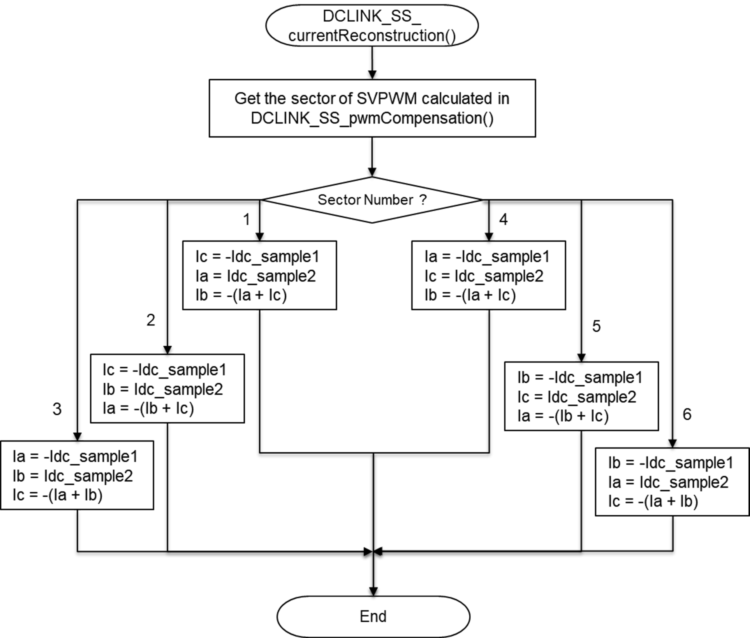
Figure 3-5 shows the flowchart of three phase current reconstruction with two sampled dc link currents and sector information. This function is called right after reading the ADC data in main control loop (mainISR).
 Figure 3-5 Flowchart of Phase Current
Reconstruction