SPRAD03 March 2022 AM2431 , AM2431 , AM2432 , AM2432 , AM2434 , AM2434 , AM6411 , AM6411 , AM6412 , AM6412 , AM6421 , AM6421 , AM6422 , AM6422 , AM6441 , AM6441 , AM6442 , AM6442
- Trademarks
- 1 System Overview
- 2 Hardware Prerequisites
- 3 Hardware Configuration
- 4 HW Pinouts, Default Jumpers, and Connections
- 5 Schematics
- 6 Jumper Settings and Descriptions
- 7 LEDs
- 8 Software Architecture
- 9 Actuation and Feedback Timing
- 10Benchmark Results
-
11Detailed Demo User's Guide
- 11.1 Step 0. Getting the Software and Building
- 11.2 Step 1. Getting Started With the Hardware
- 11.3 Step 2. Configure ROQ437 EnDat2.2 Encoder for Faster EnDat 2.2 Recovery Time (only needs to be done once the first time you use the ROQ437 encoder)
- 11.4 Step 3. Open Loop Iq Control (BUILDLEVEL == OPEN_LOOP_IQ_ID)
- 11.5 Step 4. Closed Loop Iq/Id Control (BUILDLEVEL == CLOSED_LOOP_IQ_ID)
- 11.6 Step 5. Closed Loop Speed Control (BUILDLEVEL == CLOSED_LOOP_SPEED)
- 11.7 Step 6. Closed Loop Position Control (BUILDLEVEL == CLOSED_LOOP_POSITION)
- 12Build Using MCU+SDK 08.00.00.21 & CCS 10.3.1
- 13Summary
- 14Appendix A: Detailed Motor Control R5F Processing Time
- 15References
11.2 Step 1. Getting Started With the Hardware
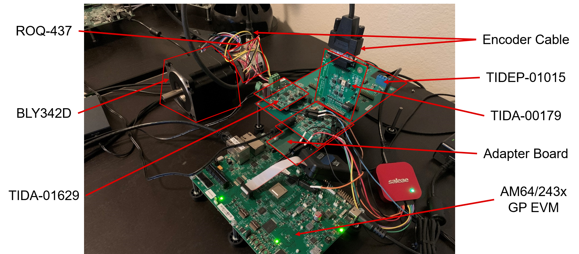
 Figure 11-1 Hardware Setup
- Plug the 5 PCBs together,
referencing the image above and the instructions below
- The Adapter Board, the TIDEP-01015 board, and the TMDS243GPEVM can only be connect together in one way, seen above. Plug those three boards together and add all the standoffs as necessary
- The TIDA-01629 power
stage board should be plugged into the first boosterpack slot that is
closest to the TMDS243GPEVM and the screw terminals should be facing the
outside of the board. This first slot corresponds to PWM0-2 as well as
SD channels 0-2
- There should be NO jumpers populated on this board
- The TIDA-00179 encoder
transceiver board should be plugged into the first encoder slot that is
closest to the TMDS243GPEVM with the right-angle connector and the DB-15
connector closest to the TMDS243GPEVM. This first slot corresponds to
EnDat channel 0
- There should be NO jumpers populated on this board
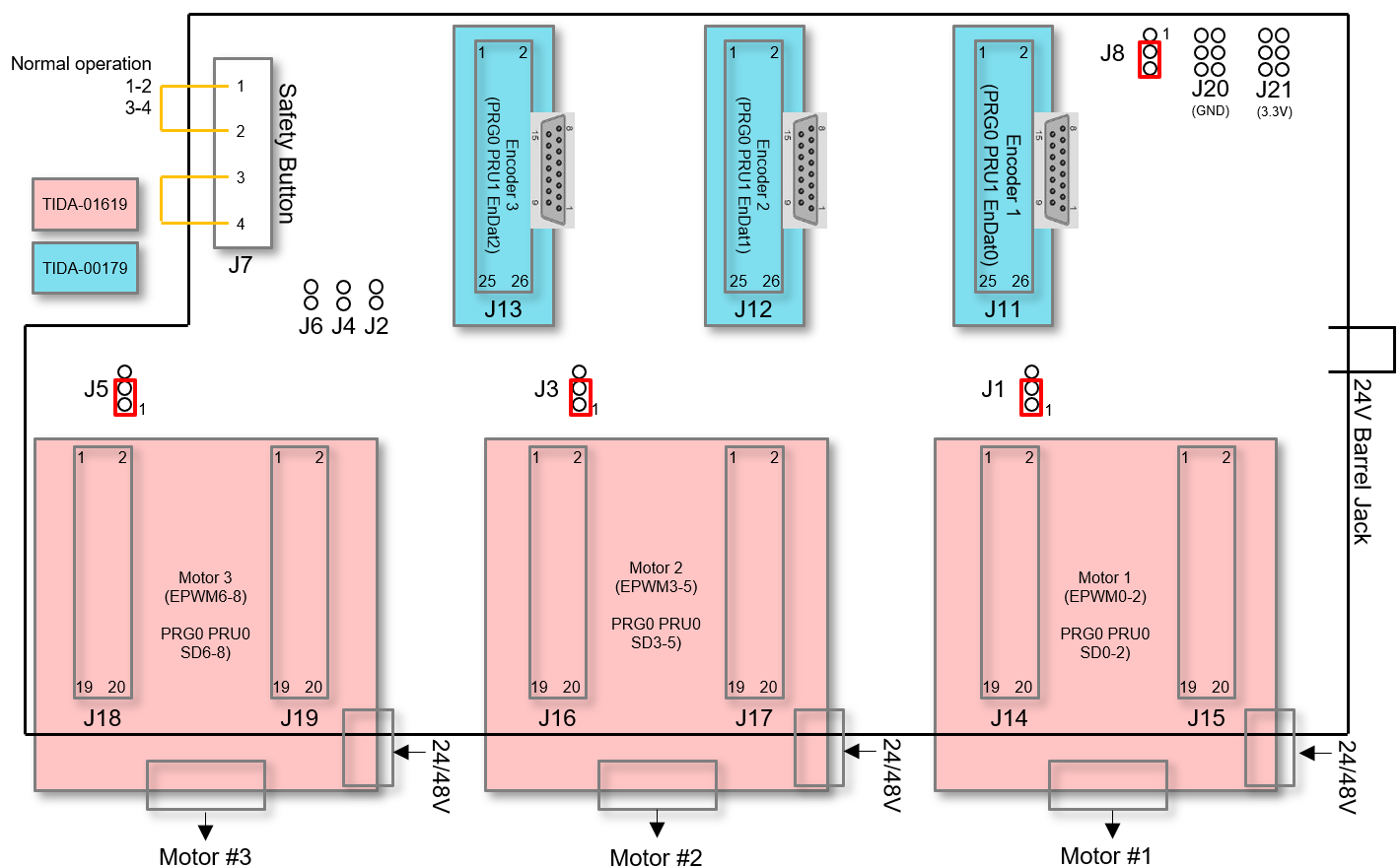
- Configure the jumpers on the
TIDEP-01015 board as shown by the red rectangles below and described in the
table. Also note that the screw terminals connectors in J7 need to be shorted as
shown in Figure 11-2 as described in the table (this connector enables an STO type function but is
currently being bypassed).
 Figure 11-2 TIDEP-01015 Jumper
Settings
- Jumper settings tableTable 11-1 Jumper Settings Table
Ref ID Description Settings Notes J1, J3, J5 FOC loop feedback source (1,2): current fb (default)
2,3: voltage fb
open: open looppin numbering starts from bottom pin (opposite of most other pin groups on the board) J2, J4, J6 ADC selection closed: SARopen: Sigma Delta (default) J7 Safe torque off switch inputs (1,2)(3,4) pins 1,2 and pins 3,4 shorted is normal operation mode. J8 Sigma Delta clock select (1,2): ECAP PWM (default)
2,3: HW delay clk
open: invalidJ20 GND J21 3V3_D
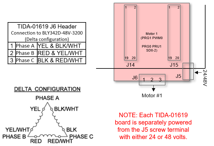
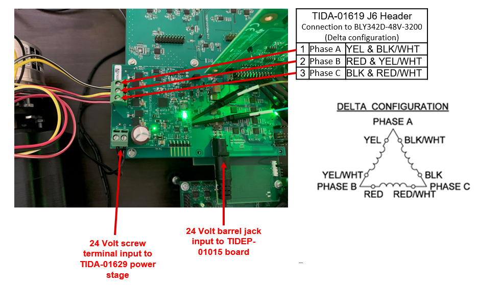
- Connect the motor wirings to the
TIDA-01629 power stage screw terminal at J6. Be sure to notice that the motor
phase wirings are the 6 thicker wires. Note: There are also 5 other smaller, single-colored wires that are for an incremental encoder that should be left unconnected.
 Figure 11-3 TIDA-01619 J6 Header
1
 Figure 11-4 TIDA-01619 J6 Header 2
- Connect the encoder cable from the ROQ-437 EnDat2.2 encoder to the TIDA-00179 encoder transceiver board
- Connect 24V to the screw terminal of the TIDA-01629 board as well as to the barrel jack connector on the TIDEP-01015 board (pictured 2 steps above). DO NOT CONNECT power to the barrel jack of the TIDA-00179 board, this board receives power through the TIDEP-01015 board