SPRAD03 March 2022 AM2431 , AM2431 , AM2432 , AM2432 , AM2434 , AM2434 , AM6411 , AM6411 , AM6412 , AM6412 , AM6421 , AM6421 , AM6422 , AM6422 , AM6441 , AM6441 , AM6442 , AM6442
- Trademarks
- 1 System Overview
- 2 Hardware Prerequisites
- 3 Hardware Configuration
- 4 HW Pinouts, Default Jumpers, and Connections
- 5 Schematics
- 6 Jumper Settings and Descriptions
- 7 LEDs
- 8 Software Architecture
- 9 Actuation and Feedback Timing
- 10Benchmark Results
-
11Detailed Demo User's Guide
- 11.1 Step 0. Getting the Software and Building
- 11.2 Step 1. Getting Started With the Hardware
- 11.3 Step 2. Configure ROQ437 EnDat2.2 Encoder for Faster EnDat 2.2 Recovery Time (only needs to be done once the first time you use the ROQ437 encoder)
- 11.4 Step 3. Open Loop Iq Control (BUILDLEVEL == OPEN_LOOP_IQ_ID)
- 11.5 Step 4. Closed Loop Iq/Id Control (BUILDLEVEL == CLOSED_LOOP_IQ_ID)
- 11.6 Step 5. Closed Loop Speed Control (BUILDLEVEL == CLOSED_LOOP_SPEED)
- 11.7 Step 6. Closed Loop Position Control (BUILDLEVEL == CLOSED_LOOP_POSITION)
- 12Build Using MCU+SDK 08.00.00.21 & CCS 10.3.1
- 13Summary
- 14Appendix A: Detailed Motor Control R5F Processing Time
- 15References
8 Software Architecture
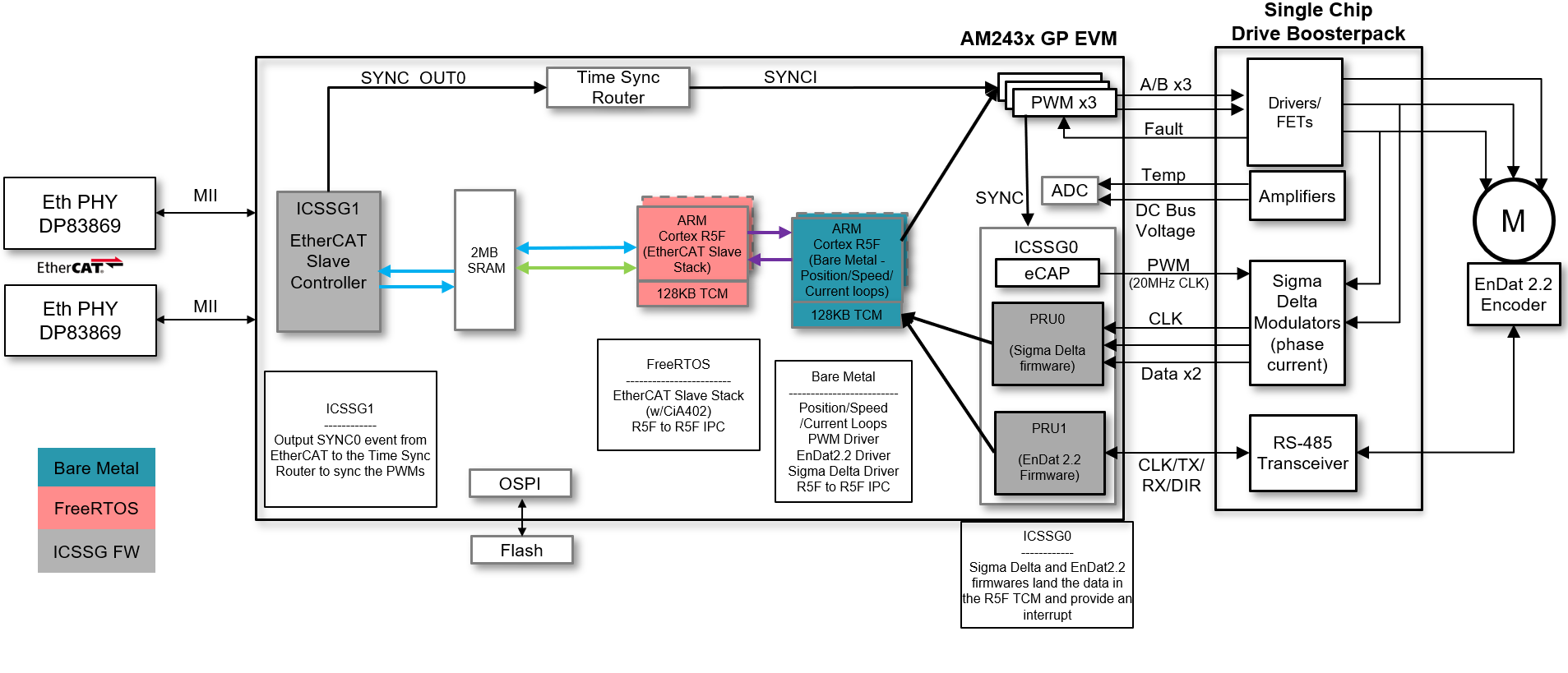
The Single-chip Servo Drive Demo was architected around a central real-time path that is made up of:
- ICSSG1 - EtherCAT Slave Controller Firmware
- R5FSS1_0 - EtherCAT Slave Stack implementing CiA402 using FreeRTOS
- IPC provided in the MCU+ SDK
- R5FSS0_0 - Closed loop FOC control capable of current, speed, or position closed-loop control
- EPWM - Enhanced PWM peripherals to generate waveforms based on the output of the FOC loop
- ICSSG0 - Sigma Delta firmware in PRU0 for phase current feedback and EnDat2.2 firmware in PRU1 for angle/position/speed feedback
This real-time path demonstrates the components needed to make up a bare-bones Servo Drive from receiving data from an EtherCAT master to closing the real-time control loops in order to precisely control a directly connected motor.
The Software Architecture diagram is shown in Figure 8-1.
 Figure 8-1 Software Architecture