SPRADH2 February 2024 AM62A3 , AM62A3-Q1 , AM62A7 , AM62A7-Q1 , AM62P , AM62P-Q1 , DS90UB953A-Q1 , DS90UB960-Q1 , TDES960 , TSER953
- 1
- Abstract
- Trademarks
- 1Introduction
- 2Connecting Multiple CSI-2 Cameras to the SoC
- 3Enabling Multiple Cameras in Software
- 4Reference Design
- 5Performance Analysis
- 6Summary
- 7References
4.2 Setting up Four IMX219 Cameras
Follow the instructions provided in the AM62A Starter Kit EVM Quick Start Guild to setup the SK-AM62A-LP EVM (AM62A SK) and ArduCam V3Link Camera Solution Quick Start Guide to connect the cameras to AM62A SK through the V3Link kit. Make sure the pins on the flex cables, cameras, V3Link board, and AM62A SK are all aligned properly.
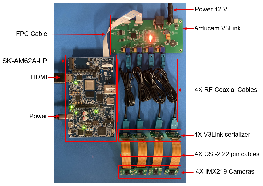
Figure 4-1 shows the setup used for the reference design in this report. The main components in the setup includes:
- 1X SK-AM62A-LP EVM board
- 1X Arducam V3Link d-ch adapter board
- FPC cable connecting Arducam V3Link to SK-AM62A
- 4X V3Link camera adapters (serializers)
- 4X RF coaxial cables to connect V3Link serializers to V3Link d-ch kit
- 4X IMX219 Cameras
- 4X CSI-2 22 pin cables to connect cameras to serializers
- Cables: HDMI cable, USB-C to power SK-AM62A-LP and 12V power sourced for V3Link d-ch kit)
- Other components not shown in Figure 4-1: micro-SD card, micro-USB cable to access SK-AM62A-LP, and ethernet for streaming
 Figure 4-1 V3link Board and 4 Cameras Setup Used in the Reference Design