SBAU382A
November 2021 – January 2022
Trademarks
1
ADS704X-5XEVM-PDK Overview
2
Introduction to the ADS704X-5XEVM
2.1
Analog Inputs
2.1.1
Single-Ended Input Path
2.1.2
Differential Input Path
2.2
Power Supplies
2.3
Digital Interface and Communication
2.4
I2C Bus for Onboard EEPROM
3
ADS704X-5XEVM Software Installation
4
EVM Operation
4.1
Connecting the Hardware
4.2
EVM GUI Global Settings for ADC Control
4.3
Time Domain Display
4.4
Spectral Analysis
4.5
Histogram Analysis
4.6
Updating EEPROM After ADC Replacement
5
Bill of Materials, Layout, and Schematic
5.1
Bill of Materials
5.2
Layout
5.3
Schematic
6
Revision History
5.3
Schematic
Figure 5-8
shows the schematic for the ADS704X-5XEVM.
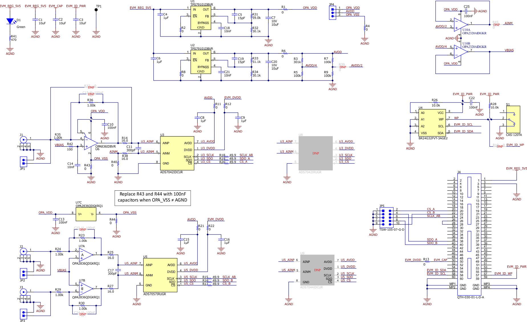
Figure 5-8
ADS704X-5XEVM Schematic