SBAU401 August   2022


  1.   DAC82002EVM
  2.   Trademarks
  3. 1Overview
    1. 1.1 Kit Contents
    2. 1.2 Related Documentation from Texas Instruments
  4. 2System Setup
    1. 2.1 Software Setup
      1. 2.1.1 Operating Systems
      2. 2.1.2 Software Installation
    2. 2.2 Hardware Setup
      1. 2.2.1 Electrostatic Discharge Caution
      2. 2.2.2 Power Configurations and Jumper Settings
      3. 2.2.3 Connecting the Hardware
  5. 3Detailed Description
    1. 3.1 Hardware Description
      1. 3.1.1 Theory of Operation
        1. 3.1.1.1 Signal Definitions
        2. 3.1.1.2 Buffer Customization
    2. 3.2 Software Description
      1. 3.2.1 Starting the Software
      2. 3.2.2 Software Features
        1. 3.2.2.1 Low Level Configuration Page
  6. 4Schematic, PCB Layout, and Bill of Materials
    1. 4.1 Schematic
    2. 4.2 PCB Layout
    3. 4.3 Bill of Materials

Buffer Customization

The DAC82002EVM has three operational amplifier circuits that can be configured using 0-Ω resistors. All three circuits act as unity gain buffers with the default resistor placement. The following figure shows the 0-Ω resistors are the only resistors that are populated on the DAC82002EVM by default.
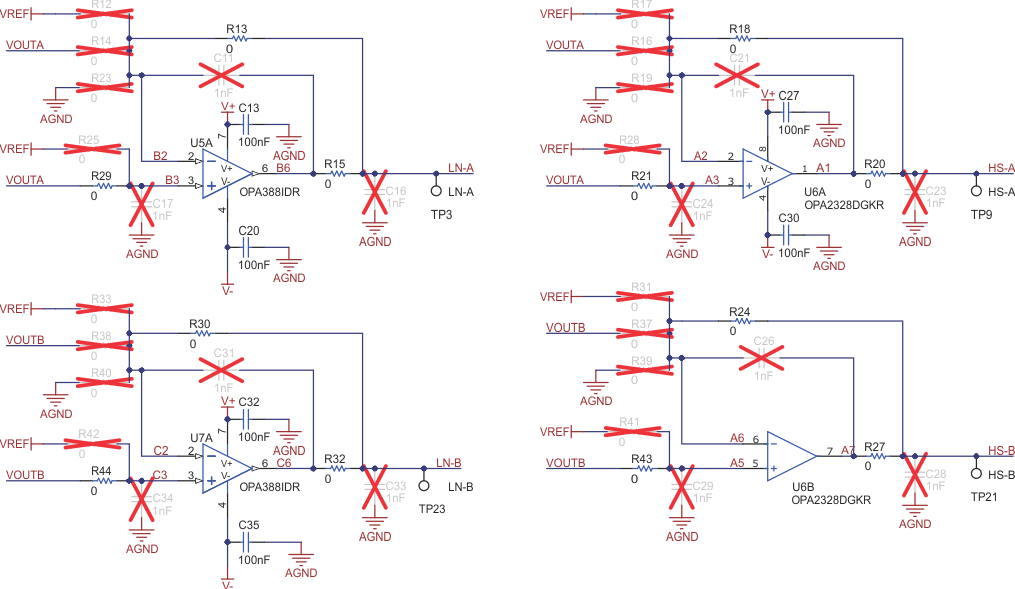
GUID-20220728-SS0I-VMMX-WJCX-HKXZ9L6D2D5P-low.gif Figure 3-2 Default Buffer Configuration

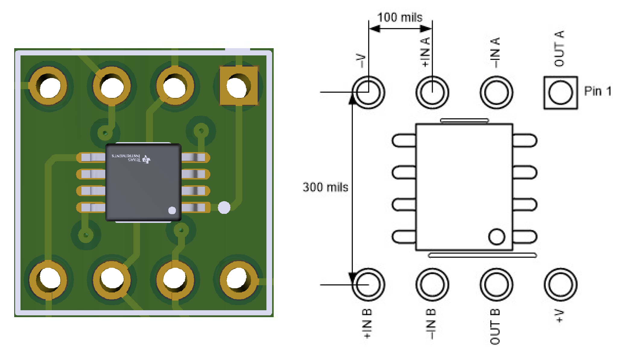
The three operational amplifiers can be replaced by the desired DIP-8 package. The inserted packages must follow the same pin mapping as the default operational amplifiers. Figure 3-3 shows the buffer DIP adapter connections.
GUID-20220729-SS0I-NVCH-GBVL-10CCJCDNH8F0-low.png Figure 3-3 Buffer DIP Adapter Connections