SBOU227A September 2019 – November 2023 ALM2402F-Q1
4 Power-Supply Connections
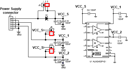
The power-supply connections for the ALM2402FQ1EVM are provided through connector J7 at the top of the EVM. Table 4-1 summarizes the pin definition for supply connector J7, and the allowed voltage range for each supply connection.
| Pin Number | Supply Connection | Voltage Range |
|---|---|---|
| J7.1 | Input stage supply (VCC) | 4.5 V to 16 V |
| J7.2, J7.4, J7.6 | Ground | 0 V |
| J7.3 | Op amp 1 output supply (VCC_1) | 3 V to 16 V |
| J7.5 | Op amp 2 output supply (VCC_2) | 3 V to 16 V |
By default, the ALM2402FQ1 is configured to use a single supply connected through J7.1 (VCC) and J7.2 (GND) with jumpers J8 and J10 set to shunt pins 1-2. Alternatively, the EVM can be configured to use three independent power-supply connections: input stage supply (VCC), op amp 1 output supply (VCC_1), and op amp 2 output supply (VCC_2). Setting jumpers J8 and J10 to shunt pins 2-3 allows the use of independent voltage supplies as indicated in Figure 4-1.
 Figure 4-1 ALM2402FQ1EVM Configured With Independent Input-Stage and Output-Stage Supplies