SCBA020A October   1999  – March 2020 TMS3705


  1.   Integrated TIRIS™ RF Module TMS3705 Introduction to Low-Frequency Reader
    1.     Trademarks
    2. 1 Document Overview
    3. 2 Introduction
    4. 3 Key Features of the TMS3705
      1. 3.1 PLL for the System Clock
      2. 3.2 Ceramic Resonator for Reference Oscillator
      3. 3.3 Full-Bridge Driver Stage
      4. 3.4 Fully Integrated Bandpass Amplifier
      5. 3.5 Multifunctional 2-Wire Interface
    5. 4 Sequence Control
      1. 4.1 Initialization
    6. 5 Circuit Description of the Sample RF Module
      1. 5.1 Oscillator System
      2. 5.2 Antenna Circuit
      3. 5.3 Pre-Amplifier
      4. 5.4 Interface Circuit to the Control Module
      5. 5.5 Antenna Coil
    7. 6 Regulatory Notices and Ordering
      1. 6.1 Regulatory Notices
      2. 6.2 Ordering
  2.   Revision History

Initialization

For proper mode control write, it is essential to know if the TMS3705 is in idle or sleep state.

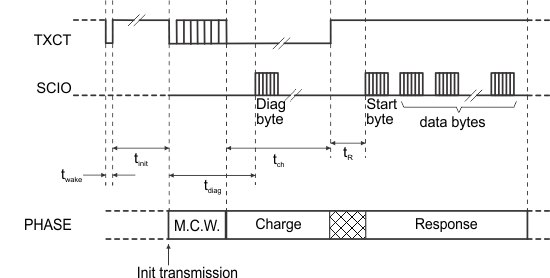
Independent of the sleep or idle state of the IC, the timing in Figure 2 can be used. The timing is given for a read-only transponder, but the wake sequence can also be used for other transponder types.

mcr_cba020.gifFigure 2. MCR Programming

The wake pulse (low) must be shorter than tmcr (twake << tmcr; twake = 50 µs typical) to avoid the wake pulse being interpreted as a start of transmission.

After the wake pulse, the TXCT signal must be high for at least the maximum of the minimum initialization time tinit min.

The proposed timing assures that an IC in sleep mode switches to idle state. If the IC was already in idle state, the wake pulse has no effect and the IC remains in idle state.