SCBA020A October   1999  – March 2020 TMS3705


  1.   Integrated TIRIS™ RF Module TMS3705 Introduction to Low-Frequency Reader
    1.     Trademarks
    2. 1 Document Overview
    3. 2 Introduction
    4. 3 Key Features of the TMS3705
      1. 3.1 PLL for the System Clock
      2. 3.2 Ceramic Resonator for Reference Oscillator
      3. 3.3 Full-Bridge Driver Stage
      4. 3.4 Fully Integrated Bandpass Amplifier
      5. 3.5 Multifunctional 2-Wire Interface
    5. 4 Sequence Control
      1. 4.1 Initialization
    6. 5 Circuit Description of the Sample RF Module
      1. 5.1 Oscillator System
      2. 5.2 Antenna Circuit
      3. 5.3 Pre-Amplifier
      4. 5.4 Interface Circuit to the Control Module
      5. 5.5 Antenna Coil
    7. 6 Regulatory Notices and Ordering
      1. 6.1 Regulatory Notices
      2. 6.2 Ordering
  2.   Revision History

Interface Circuit to the Control Module

The RF module control input TXCTL activates the transmitter if it is low level. To prevent transmitting continuously if the line to the controller is accidentally interrupted, resistor R7 pulls the signal up to high level. This TXCTL control line transfers the modulation signal and the mode control byte. To improve its electromagnetic susceptibility, a low-pass RC filter R6/C6 is introduced to this line.

The RX data output SCIO of the IC is protected against a short circuit to GND by the serial resistor R5.

In case of a very noisy environment and long signal lines between the RF module and the control module, additional circuitry might be needed to avoid damaging the IC terminals by overvoltage or malfunctions by corrupted data.
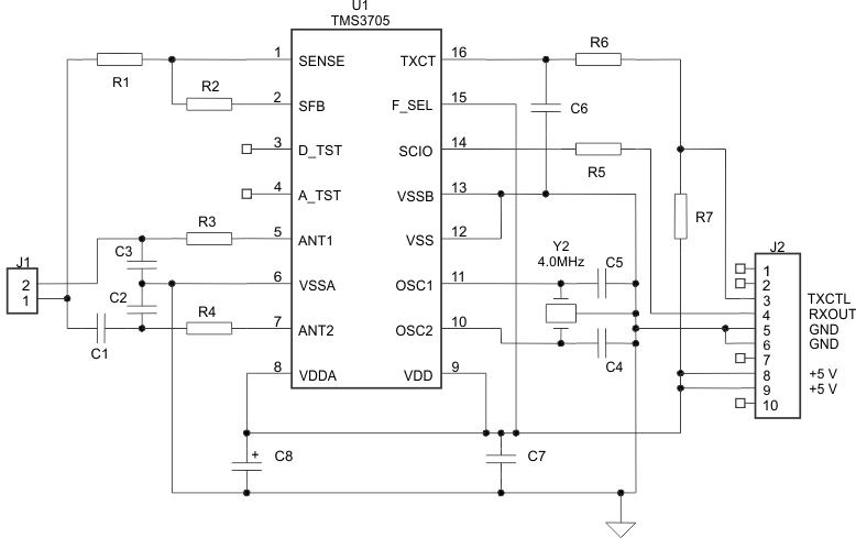
schem_cba020.gifFigure 3. Schematic Diagram for Sample RF Module

Table 1. Component List for Sample RF Module

Position Reference Description Shape Value
1 U1 TIRIS ASIC SO16 TMS3705
2 Y1 Ceramic resonator 3 pin 4.0 MHz
3 C1 Ceramic capacitor 1210 3.3 nF, 100 V or higher, NPO, COG, 2% matching with antenna coil
4 C2 Ceramic capacitor 0603 220 pF, 50 V
5 C3 Ceramic capacitor 0603 220 pF, 50 V
6 C4 Ceramic capacitor 0603 (10 pF) see description
7 C5 Ceramic capacitor 0603 (10 pF) see description
8 C6 Ceramic capacitor 0603 1 nF, 50 V
9 C7 Ceramic capacitor 1206 0.1 uF, 50 V
10 C8 Tantalum capacitor D 22 uF, 16 V
11 R1 Resistor 0603 47 kΩ
12 R2 Resistor 0603 150 kΩ
13 R3 Resistor 1206 4.7 Ω
14 R4 Resistor 1206 4.7 Ω
15 R5 Resistor 0603 220 Ω
16 R6 Resistor 0603 1 kΩ
17 R7 Resistor 0603 10 kΩ
18 J1 Connector R= 2.54 mm 2-pin female
19 J2 Connector R= 2.54 mm 10-pin male

Table 2. Pin Assignment of the Connector J2 of the Sample RF Module

Pin Number Pin Function
1 Not used
2 Not used
3 TXCTL–
4 RXOUT
5 GND
6 GND
7 Not used
8 +5 V
9 +5 V
10 Reserved for +12 V